 Maarten Janssen
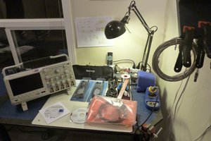
A few days ago I was cleaning out a small storage room in my house. I found an alarm clock that I had put in there a few years ago because its display was much too bright. My initial intention with it was to dim the display and put it back into use, but that never happened, it got replaced by a simple cheap alarm clock and it ended up in a closet. So I decided to tear it apart to see if there was anything interesting in there and to maybe harvest some components.
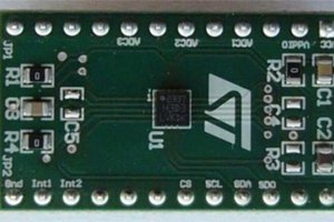
Apart from some components I could harvest I noticed a small PCB dangling off the main board marked 'Radio'. It had a single RDA5807FP chip on it and a few additional components. I googled the part number and found a datasheet for the device. Turns out it's an FM radio in a chip! And it's a quite capable one, controllable over I2C!
It turned into a little surprise project! I got one of my Arduinos out and connected the board and some cheap external speakers with a built-in amp. The datasheet of the 5807 nicely describes the functions of the chip's registers. It still took me quite a while to figure out how to get some sound out of the thing. I wanted it to be a learning experience so I didn't look into any code that may already be available to control the 5807. After lots of trial and error and just random pops from the speaker I finally got it to produce some sweet whit noise!
In the process I blew up the 3.3v regulator on the little board by hooking up the ground to the 5V supply on the Arduino, but luckily the 5807 was unharmed. Hence the jumper that I soldered onto the board :)
Switching on the radio and tuning
The sequence to switch the radio on turned out to be:
- R2: Enable the radio, Enable soft reset
- R3: Set up the correct band and channel spacing (EU FM band and 100KHz spacing in this case)
- R5: Setting the correct antenna port, Signal to noise ratio and a volume
- The other registers are cleared
Now the radio can be switched on by
- R2: Disabling soft reset, disabling mute and enabling audio output
- R3: Enable tuning
Once this is done the rest is quite straight forward. Tuning the radio to a frequency is easy by taking into account the current band and channel spacing setting. In my case frequency to tune to = (frequency - 87) / 0.1. I can reverse this formula to get the frequency display on screen when I read the current frequency form the 5807.
The Arduino is constantly communicating with the 5807 by reading its 6 status registers. With this I can update the current frequency, signal strength, RDS etc.
Decoding the channel name
The 5807 also supports RDS which turned out to be a whole new experience to get working. I had no prior knowledge of RDS so finding out how it works was interesting. I found some good documentation about the different RDS messages here: http://www.g.laroche.free.fr/english/rds/groupes/listeGroupesRDS.htm. The 5807 will set a flag when new RDS data is available. Through some more trial and error I found out that when handling an RDS message you best toggle the RDS enable of the 5807 to reset this data flag, otherwise you may be dealing with an old message which can be problematic...
the four RDS blocks are each stored in a separate register C through F. The 5807 only detects errors on block A and B, not on blocks C and D, which contain the actual data! So to read the channel name I first look if there is any new RDS data and if there is that the error bits of block A and B are all 0. Now I can look for the so called group number in block B. If I detect a group A0 or B0 we're receiving channel tuning data that also contains part of the channel name.
The channel name is 8 characters long and transmitted 2 characters at a time in block D. The last two bits of block B tell the offset of the characters in the channel name. Now since the 5807 doesn't tell me anything about the quality of the data I only accept a part of the channel name if I receive the same characters at the same position twice in a row.


 MagicWolfi
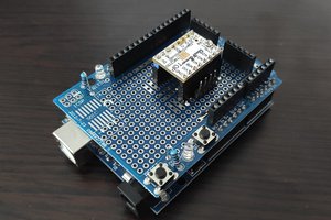
 Radu Pascal
 Emach00
seems I'm having trouble with tuneTo() function as it does not tunes to correct frequency. anyone have any idea the reason?
setup routine this works, but in the loop if i set to certain station which I've save in eeprom (like say ), it goes to like a weird frequency like 112.5.
I was able get this sorted out by incorporating this function copied from https://funprojects.blog/tag/rda5807/
void Radio::tuneTo2(int freq) {
int freqB;
byte freqH, freqL;
freqB = freq - 870; // chip needs to have freq offset from lowest freq (870)
freqH = freqB>>2; // you need to break the offset freq into 2 parts (hi/low)
freqL = (freqB&3)<<6; // Shift channel selection for matching register 0x03
Wire.beginTransmission(0x11);
Wire.write(0x03);
Wire.write(freqH); // write High freq byte
Wire.write(freqL + 0x10); // write Low freq byte
Wire.endTransmission();
}