 Alex
Alexsome kind of combination of :
@davedarko's #PCB word clock and
@Daniel Rojas's #Micro Word Clock
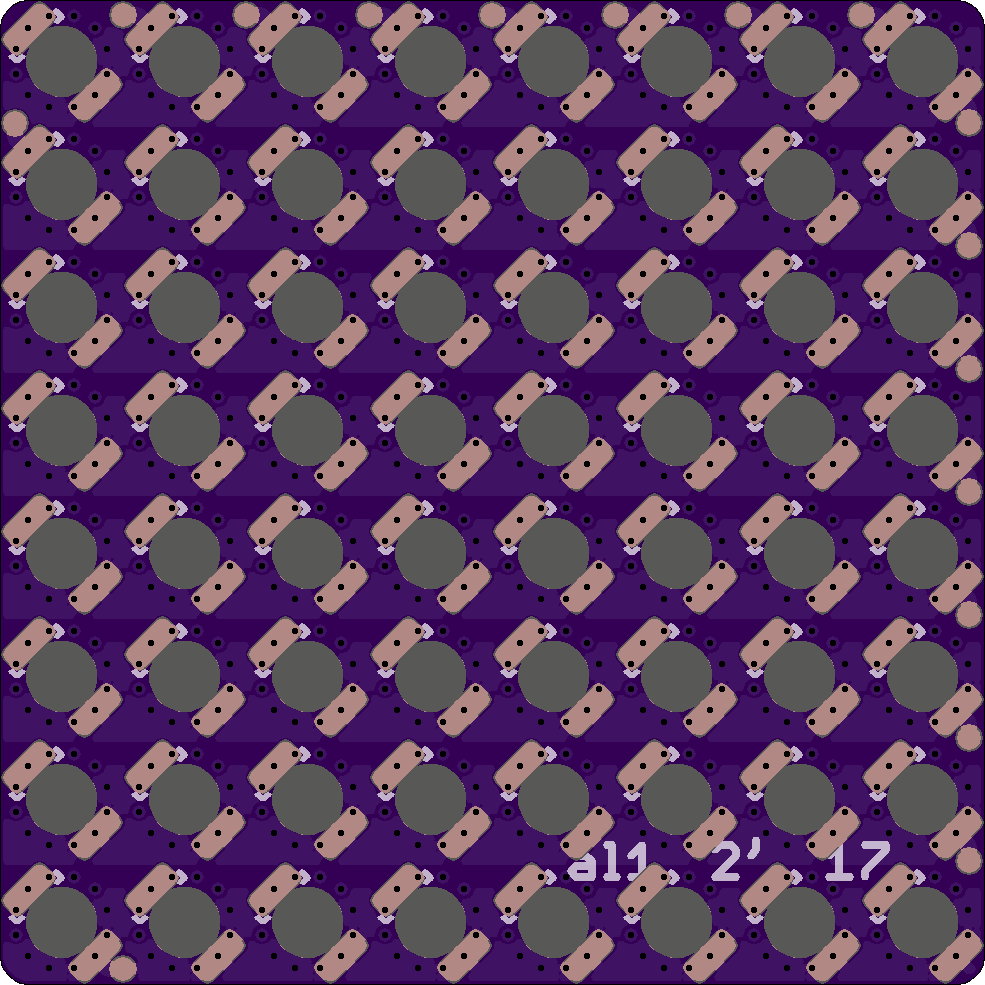
A 8x8 PCB based German Word clock with LEDs shining through the PCB. As LEDs I will use LEDs with are made for reverse mount (link Osram Datasheet). I also added vias to avoid bleeding/overlapping of light. Not really sure if needed or not but there is is enough place for vias.

PCB preview rendered with OSH-PAak's web interface
PCB Back

Used LED type (image from Osram's website)
Some facts:
- LEDs wired as normal 8x8 Matrix
- Connection by wires attached to the test pads at the side or directly at LED pads
- The LEDs were first the board was designed to this type of LEDs
- The dimension is 5x5 cm so cheap Chinese manufacturing would be possible.
- Controlling Planned with Some kind of microcontroller board without pin headers (Arduino Nano or similar) Wired to the row/coll connectors on the back
- PCB is not yet ordered (after midnight).
Discussions
Become a Hackaday.io Member
Create an account to leave a comment. Already have an account? Log In.
Link to pdf is broken: nere is a new one https://dammedia.osram.info/media/resource/hires/osram-dam-2493795/LO%20T776.pdf
Are you sure? yes | no
Nice! :)
Are you sure? yes | no
nice work, as always great to see your spin on stuff :) could you show the backside, please? :)
Are you sure? yes | no
thanks :)
Are you sure? yes | no
Another possibility for controlling bleed-through might be to use a copper mask layer on the LED side. If you use a relatively small hole in the copper right near the center of the LED, this would reduce leakage to neighbor LEDs. Of course, it will also reduce brightness and create a "halo" effect on each letter, so it might take some experimentation to get it perfected.
It makes me want to create a test board using a bunch of different techniques for comparison - vias/no vias/copper masks/no copper masks/etc and whatever other ideas there might be.
Are you sure? yes | no
that's what I had in mind for improving my display :) just play around with the whole size on the LED side. But I think the vias will improve the behaviour already, because there is less diagonal bleeding then there is vertical or horizontal bleeding and there are vias between the LEDs on their diagonal axis. The distance between characters of @al1 s board will also improve bleeding by a lot. I was constraining me to a very small size with my design, 5x5 might be a big improvement on that part. having a 11x10 charlie plexed matrix on a 5x5 board seems to me like the perfect "best of both worlds" ATM.
Are you sure? yes | no
Thanks for the comments some notes from my side:
- I added the Backside image to the log
- There is some kind of copper mask on the LED side made with wide traces
- Test boards would require min a 3x3 Matrix so that you have also on middle LED
- The bigger distance is given by the used LEDs (I selected the LEDs first and was happy that it fits inside 5x5cm)
- The LEDs are wired as normal Matrix
Are you sure? yes | no
You might get slightly better result if you stagger the vias between adjacent letters.
Are you sure? yes | no
That's a good idea, thanks. Will try that tomorrow. Comments like yours are also a benefit of posting before ordering
Are you sure? yes | no