 Dev Joshi
Started as a school project from years ago that I can't put away. Currently looking at using a different MCU to make it tick.
0%
0%
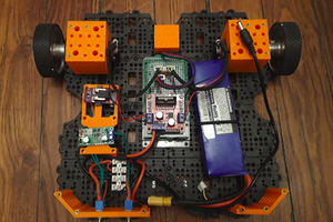
Seek_r
Seek_r is an autonomous rover designed for exploration. Fitted with a number of sensors, can navigate spaces & react to the things it finds.
Become a Hackaday.io member
Already have an account? Log in.
Just one more thing
To make the experience fit your profile, pick a username and tell us what interests you.
Pick an awesome username
hackaday.io/
Your profile's URL: hackaday.io/username. Max 25 alphanumeric characters.
Pick a few interests
Projects that share your interests
People that share your interests


 matop
matop
 Marcos
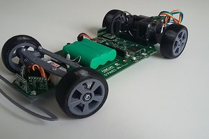
 AdaCore