 Nicholas Amrich
The ATX supply should have as high an amperage output at +12V as possible. You will need to hardwire the ATX on by connecting “PS-ON” (green wire) to ground. All yellow wires should be tied together to form the +12V rail, and all black wires tied together to form the ground. All other power wires can be clipped off.
The MOSFETs, diodes and capacitors all need to be able to withstand at least 3.14 times the input voltage. In this case, that's a 12V supply, so a modest 40V will do.
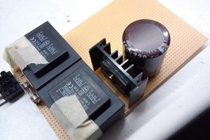
MOSFETs Q1 & Q2 should be selected for as low an on-resistance as possible. The ones found on mainboards/UPS backups work great. The drain pins of Q1 & Q2 are NOT common, so when mounting them to a heatsink, make sure they are insulated with thermal pads & washers.
Diodes D1 & D2 should be fast Schottky type. Nothing special.
C1 represents a capacitor bank made from MKP type AC capacitors. They should have as low an ESR as possible and ideally be designed to work at high temperature. Spreading the total capacitance across several physically large, low capacitance units is a good way to prevent overheating. Note that since this heater will only be running on 12V, it is necessary to lower the tank circuit frequency by adding more capacitors in order to get a useful amount of power into the workpiece. The bank I ended up with was around 8-10uF total.
Meter M1 is made using an analog meter of any type. A small length of thin stranded wire is run across the two terminals of the meter. The wire acts as a low value shunt resistor, dropping a small amount of voltage as current increases, deflecting the meter. By trial and error, it's pretty easy to find what length of wire will cause the meter to fully deflect when the power supply is under maximum load.
Switch S1 is used to toggle power to the ATX supply. It is installed between the power cord and the AC side of the ATX supply (Note that for clarity, only the DC output of the power supply is shown in the schematic.)
Switch S2 is a high current DC switch. The one I used was scrounged from an emergency car starter box. You'll need to find one that uses very heavy gauge contacts, regular AC switches will have too much resistance and burn up!
Coil L1 is the work coil, it should be around 12 turns of heavy copper wire. I used enameled wire, and the coating held up even under high temperature. This insulation is nice to have, it prevents damage to the circuit if you accidentally bump into the coil with a workpiece.
Coils L2 & L3 are heavy duty choke coils. They essentially block oscillations in the tank circuit from feeding back into the power supply. By using choke coils like this, you avoid having to add a center tap to every work coil that you use. To allow the tank circuit to run at lower frequencies, these inductors should be a high value in the millihenries. They do not need to be matched in value, but they should both be fairly low resistance to prevent overheating. I used a heavy duty toroid with 100's of turns for one, and the primary side of a SMPS transformer for the other.
Keep the wiring as short as possible.
This circuit has to deal with a lot of power, so you're better off
building it on copper-clad instead of a protoboard. All lines shown
in bold on the schematic should be made using heavy wire/tinned
copper traces. Take special care when making connections to and from
the board; any resistance due to corrosion, spring clips, pins etc
will get immensely hot. I made the mistake of using a steel bolt as
a conductor for part of the tank circuit. The comparatively high
resistance of steel caused it to get so hot that it burned the PCB
and liquefied a portion of the solder! Bolts should only be used to
clamp a copper wire directly to a tinned surface.
The chassis selection and construction is left as an exercise to the reader. Wood or plastic are OK choices, but they can be easily burnt or melted by components or a workpiece. Metal boxes are safer, but you will have to mount the work coil...
Read more »

 marble
 Yann Guidon / YGDES
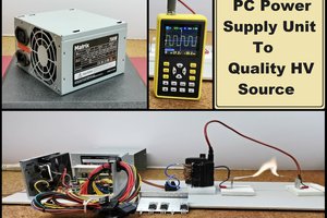
 mircemk
 ElectroBoy