 Ted Yapo
I have an idea for an augmented reality (AR) electronics workbench system. I intend to combine an overhead camera and projector with some computer-connected instrumentation and software to make a versatile system for building and debugging hardware projects.
Most people's first experience with AR is with camera-only systems which generate augmented images, perhaps on a smartphone. In contrast to these systems, projector-camera systems project the augmentation back into the "real world". Although the hardware cost for a projector-camera system is larger, they can produce much more intuitive and useful augmentation.
The block diagram for the system I have in mind is shown here:
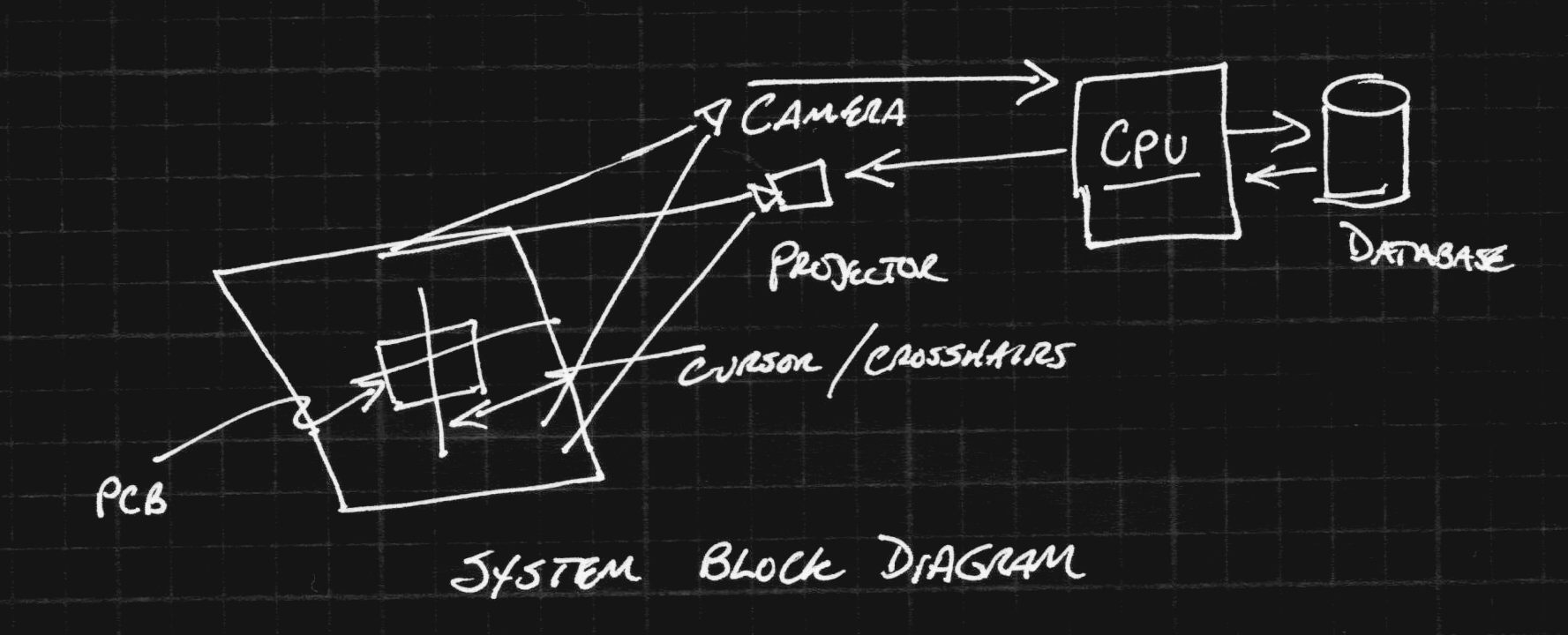
In this system, a camera is positioned over a section of a standard workbench. Images captured by the camera are processed on a common CPU (maybe on a Raspberry Pi) to detect objects on the workbench. Output from the system is projected back on to the workbench with a projector mounted overhead. Once the camera and projector system are calibrated, a mapping from camera image pixels to projector image pixels can bes established. Then, objects detected by the camera can be augmented with information projected on them. For example, the projected data could help locate parts position for manually populating an SMD PCB. This ans several other modes are discussed in more detail below.
Goals
The design goals for this system include several modes. These are what I've thought of so far. If you can think of other interesting modes, please let me know.
Interactive Benchtop Instruments
In this mode, virtual displays from DMMs, oscilloscopes, logic analyzers, and other instruments can be projected on the benchtop surface. The camera can be used to find a clean place on the bench to project the display. For example, when probing with a voltmeter, the reading can be projected near the probe point, and can persist after the probe is moved to measure another point. Many instruments are communication-enabled these days, and any of them could conceivably be connected this way.
CAD-Guided Assembly
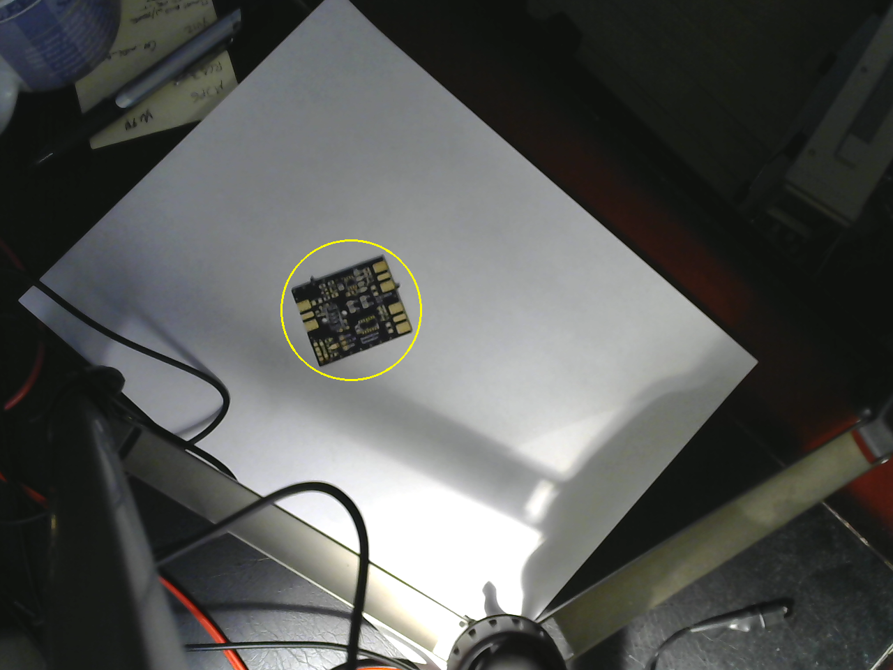
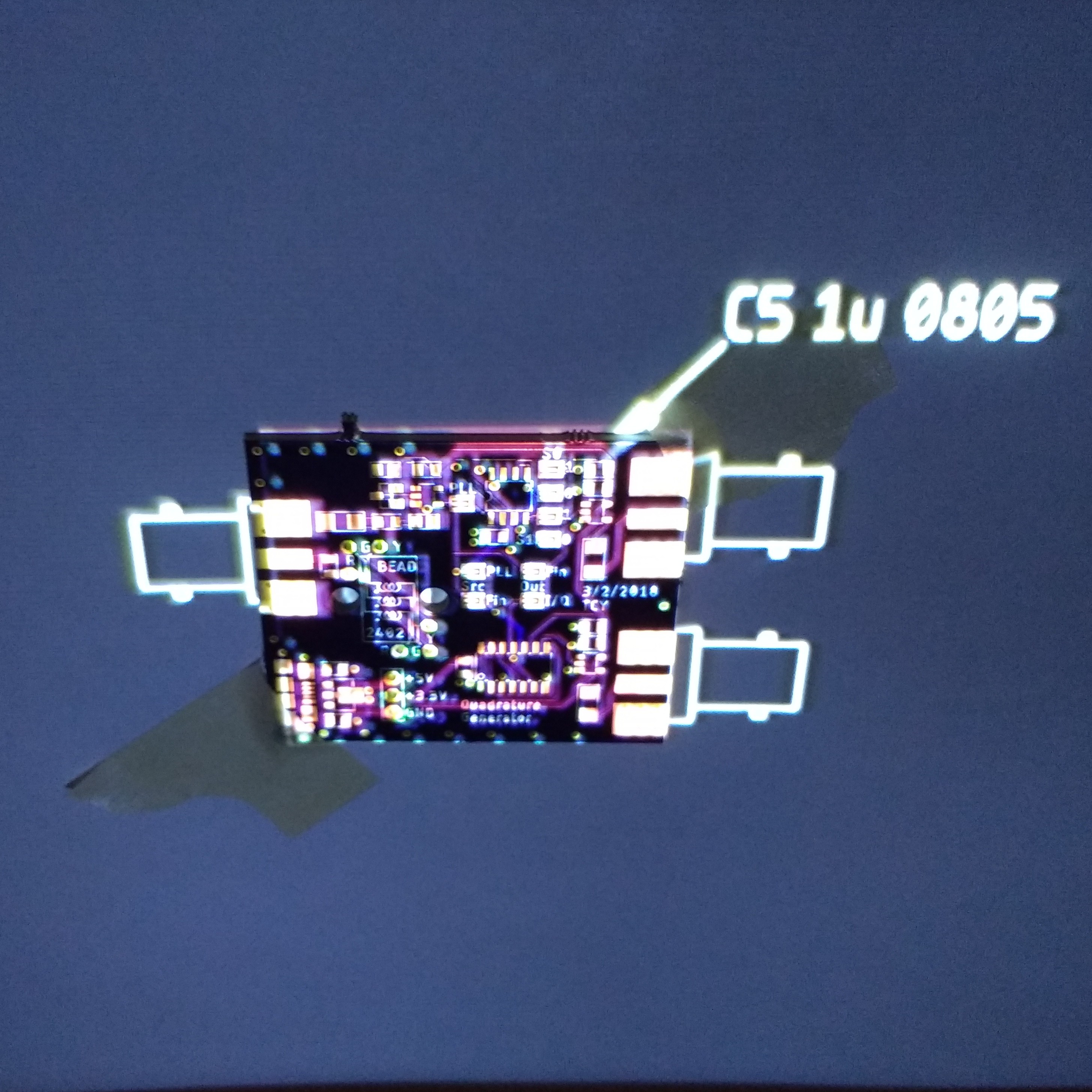
Modern PCB CAD packages (for instance Eagle or KiCAD) really streamline the creation of printed circuit board designs. But, what happens when it's time to assemble the prototypes? Which components go where? This mode aims to solve that problem. Non-projective AR has previously been applied to this problem, but I think projector-based AR is the ideal solution. In this mode, the overhead camera finds the orientation of the PCB, possibly using some fiducial markers at the corners. Once the PCB has been found, the projector can project a cursor or marker on the PCB showing the location and orientation of any of the components. Think of it as a pick-and-place machine where you are the end effector.
3D Scanning
Once you have a calibrated camera and projector, a 3D scanner is just a little bit of software. The projector can illuminate the scene with gray-coded binary structured light patterns, so that each pixel gets a unique sequence of values. When captured by the camera, this gives a correspondence between the camera pixels and the projector pixels - solving the stereo vision correspondence problem in a robust way. You will be able to generate point clouds from 3D objects that can then be combined into full 3D models (using external software).
Heat Map
By adding an inexpensive thermal camera to the system, a heat map could be projected directly on the PCB. Although the color of the PCB and components may make this difficult to see, modes might be created where hot-spots could be shown, or temperatures read by simply pointing at them with a probe.
I worked on two such systems about a decade ago, one on a table-top,...
Read more »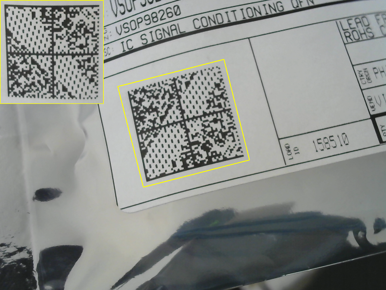


 alex
alex
 Jacob David C Cunningham
Dude that's amazing. Could help a lot to live stream as well! Keep it up!