 Ted Yapo
I found some time to mock up the camera side and the projector side today. I didn't do any calibration for either of these tests - I just wanted to get something done. On the vision side, I can find a PCB fairly reliably on a whitish background, which I think is a reasonable requirement for the you-pick-and-place mode:
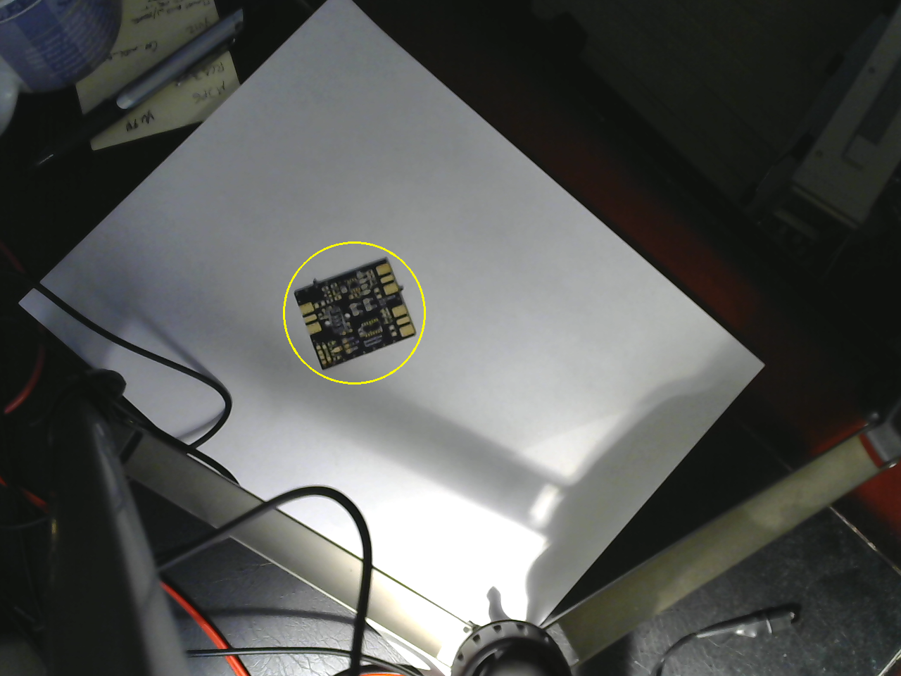
I used thresholding in HSV color space followed by morphological dilation, connected components analysis and then size-pass filtering. This will be easier once I include a model of the PCB - the idea is that you can use the gerber files (and some other data extracted from the CAD program) to more easily find and orient the PCB in the frame.
There are two issues unresolved. First, the resolution of this camera isn't great. I'm going to consider using a Raspberry Pi camera, which will also allow me to select a different focal length lens. Second, I still need to find a robust solution for finding the PCB's orientation. I have several ideas, but it will take some time to implement them. I'm wary of keypoint-based approaches, since the PCB's appearance changes as you populate the components.
Projection
I also tested the projection side with a mocked-up program. The image was exported from Eagle as a test, and the PCB was very roughly aligned to show how it will work. In this case, it is showing the location of C5.
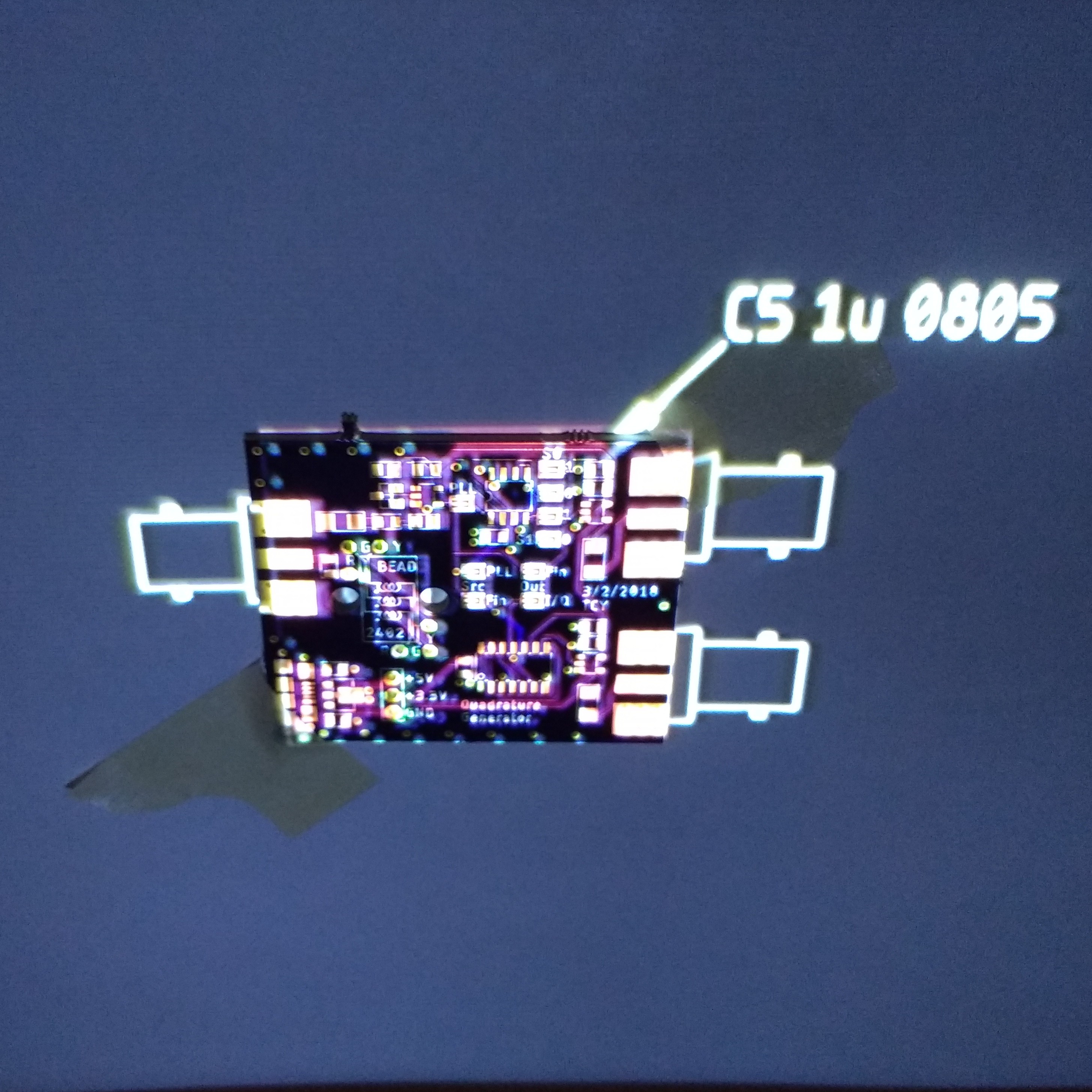
The PCB is actually taped to the back of a door in this image, since I don't have a frame for downward-projection yet. You can see the image and the PCB aren't very well aligned. Once the projector has been corrected for radial distortion and geometrically calibrated, this will look much better. It probably doesn't make much sense to project all of the information shown here; just the current part and some registration marks to ensure the PCB was detected correctly.
There are also errors in the image because the PCB surface is not at the same depth as the background. This can be corrected by using a 3D model for the PCB and texture mapping the image on it before projection. Once the camera and projector are calibrated and registered into the same 3D coordinate frame, this kind of projection is straightforward.
I am thinking I need more resolution on the projector, though. The 800x480 might work for a smaller bench area, but for a full workspace, a HD projector (or several lower-res ones) would be helpful.
3D Scanning
I also realized that once the camera and projector are calibrated, the system can be used as (fast!) 3D scanner by projection of structured light patterns. I wrote code to do this years ago, but see now that a similar gray-code binary structured light pattern generator is included in OpenCV. Using this, it should be easy to add 3D scanning to the system.
Next Up
Calibration
Discussions
Become a Hackaday.io Member
Create an account to leave a comment. Already have an account? Log In.