 Nick Sayer
Well, I thought I had solved the previous issue nicely by adding a near-zero volt reference and using the analog comparator. Alas, we're not completely out of the woods.
Here's a view of the ADC input pin with the sim in state D:
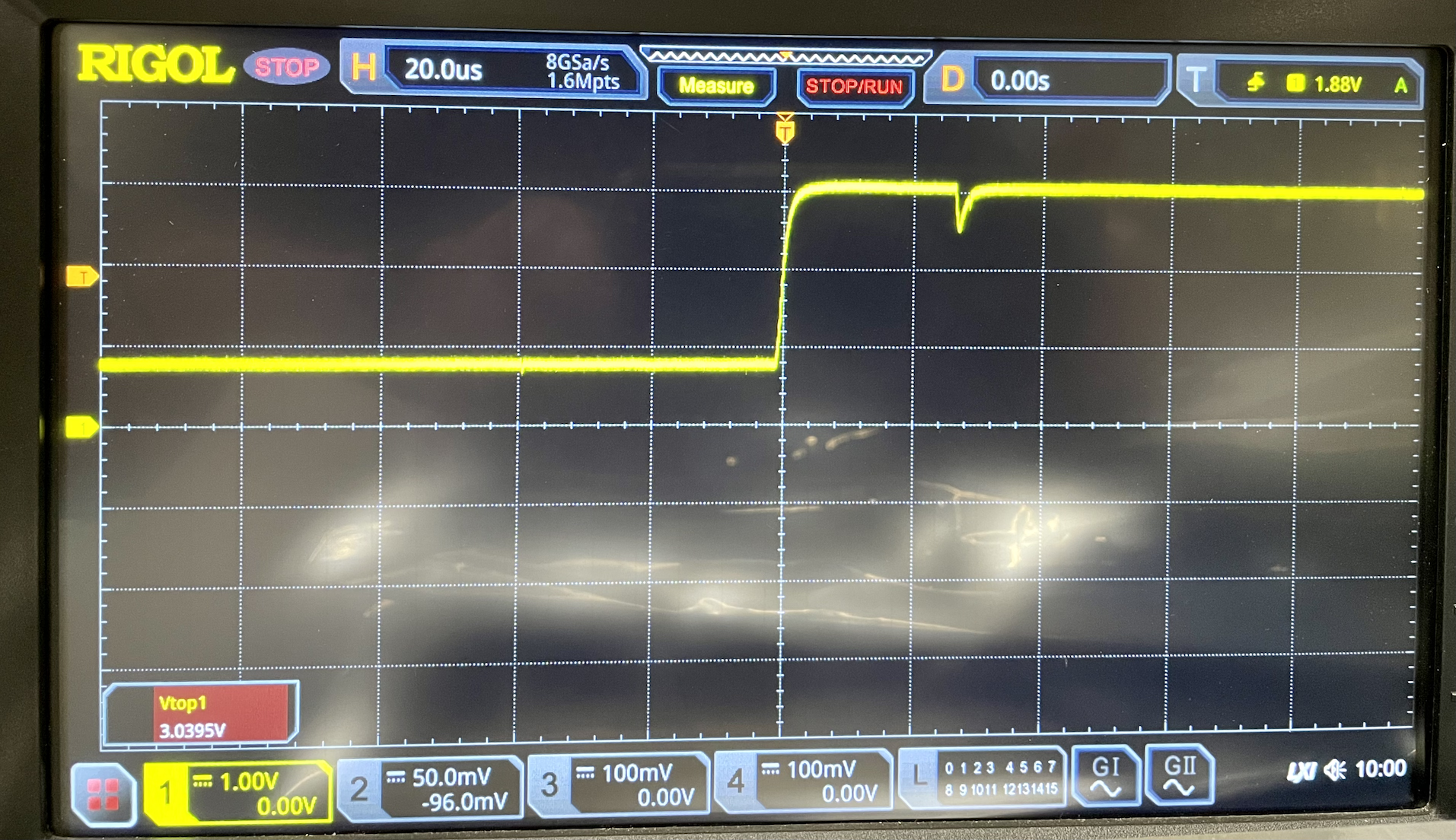
That little 0.5V downward tick is caused by the ADC sample-and-hold. The issue is that the impedance of the divider network is quite high, and the datasheet recommends no higher than 10 kΩ of output impedance into the ADC. That 3 volt level (coincidently) represents a 3 volt input. Dropping a half volt from that drops the ADC sample voltage down to 2.5 volts, which is the reference for the analog comparator. The result is screwy duty cycle readings.
It's probably adequate to work around this by simply reducing the reference voltage, The little downward ticks don't really have any ill effect beyond this. Another solution would be to add an op amp impedance buffer. I'll probably build a board to see what that looks like, but for now I suspect I'll lower the reference voltage just a little bit.
EDIT: I lifted the analog input pin and tacked in a GP SOT23-5 op amp wired as a buffer. With that, the effects of the high impedance on the ADC disappeared and it works perfectly.
I have some inventory of the boards without the amp footprint and will go ahead and use those up with a slightly lower-than-zero AC reference input, but with the op amp I think it's essentially perfect.
EDIT #2:
The correct voltage divider for the AC is 10kΩ high and 12kΩ low. With a 5 volt Vcc, that results in 2.71V, which is very close to an input side voltage of 0V. Swapping those two results in 2.27V, which represents -3V, but is low enough to work around the "ticks" seen above. While lowering the AC comparison like that is somewhat less than perfectly accurate, it won't do any harm when working with compliant systems, as the expectation is that the negative should stay close to -12 volts. The worst case scenario is that mode D with a missing diode may not hit both sides of the comparator, but that's two unlikely circumstances (missing diode and mode D) happening simultaneously.
Discussions
Become a Hackaday.io Member
Create an account to leave a comment. Already have an account? Log In.