 Jan B.
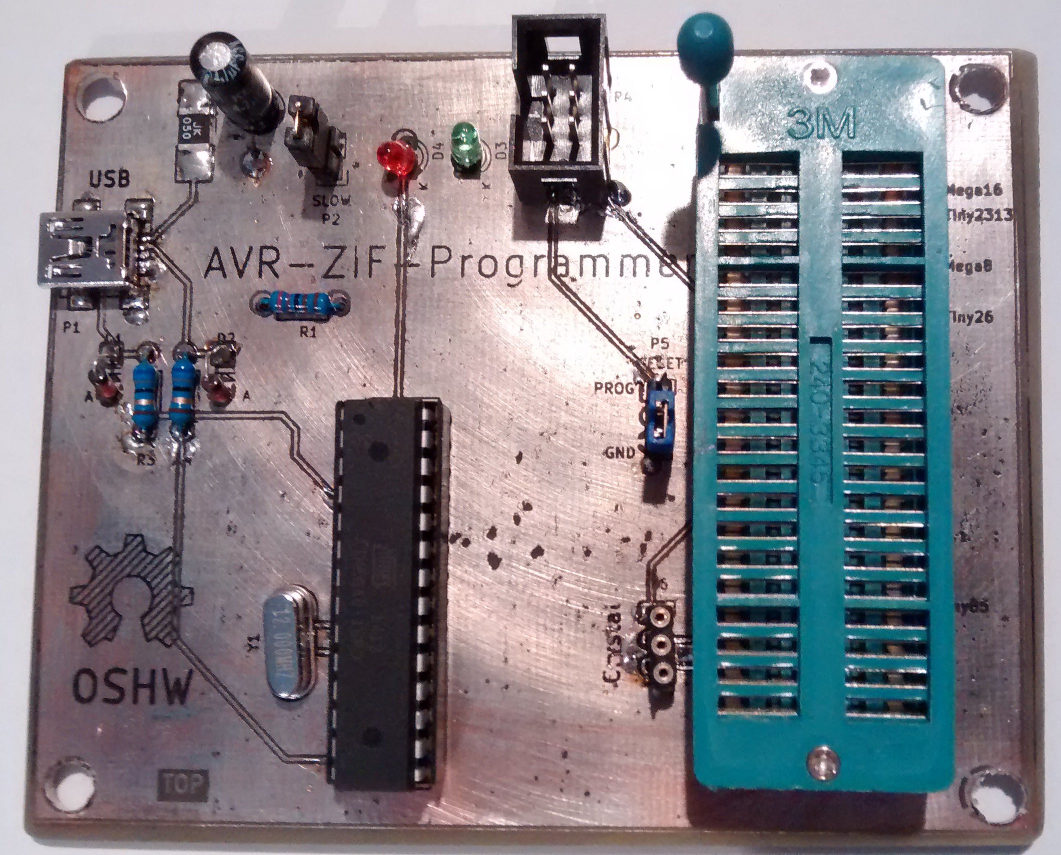
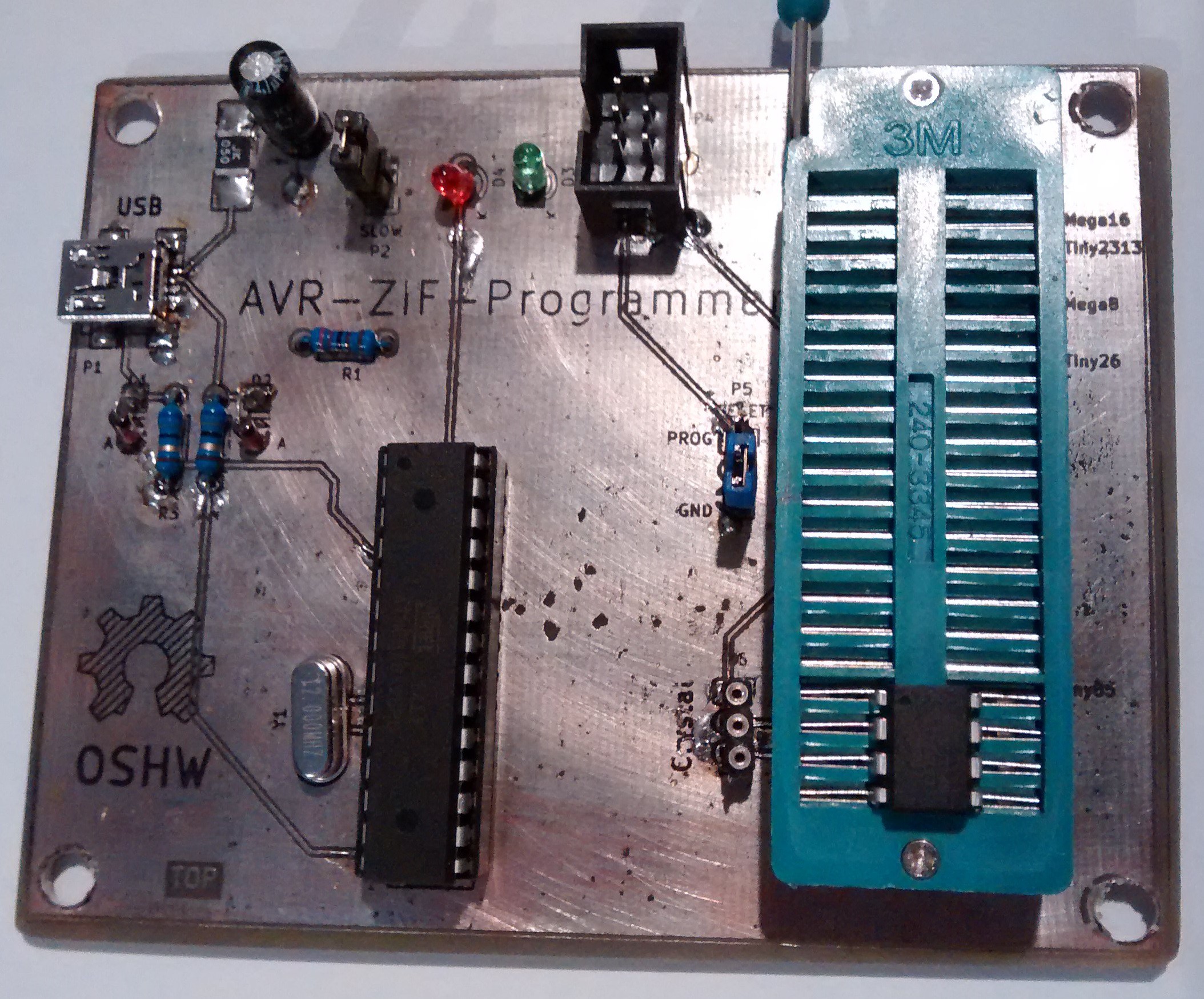
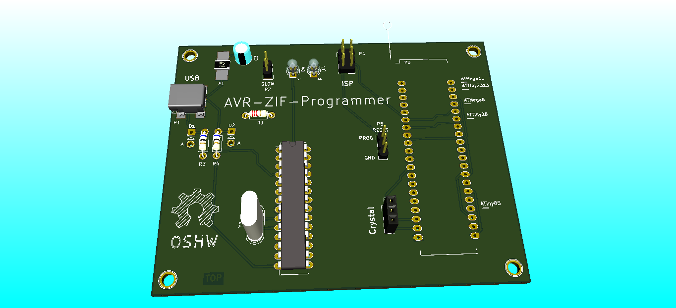
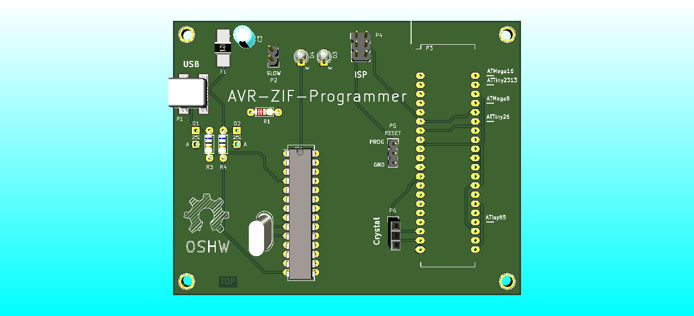
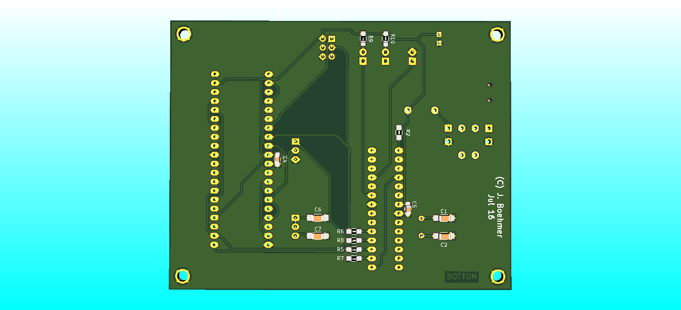
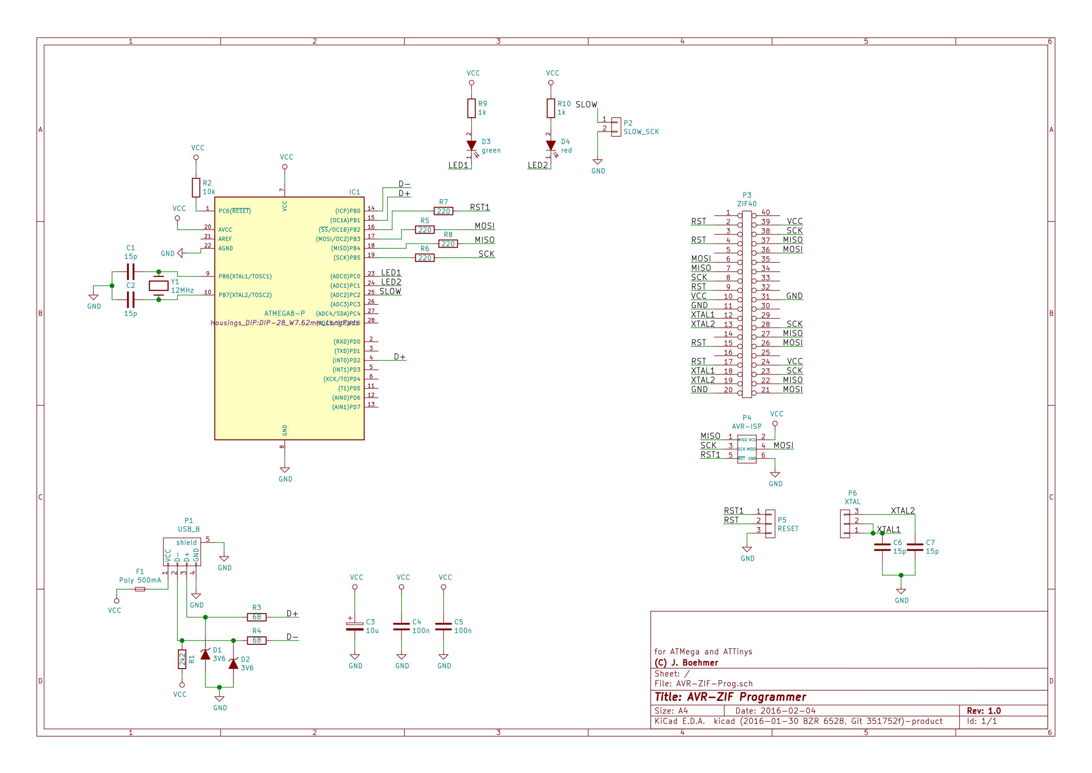
Features:
- based on USBasp by Thomas Fischl
- ISP-Connector on PCB
- can Program many different AVRs:
- ATMega 164/324/644/1284/16/32
- ATMega 8/48/88/168/328
- ATTiny 2313/4313
- ATTiny 26/261/461/861
- ATTiny 25/45/85/13
- socket for Crystal/active Clock Source
- main AVR can be updated/reflashed via USB
- LED shows data transfers

 pondahai
 Michael Delaney
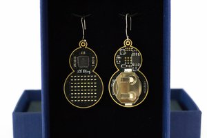
 Mahesh Venkitachalam
 Jarrett
Hi I had an idea for slot loading cartridges and ZIF alternative. The metal should clamp down like a guitar capo. The game cart or chip is inserted then a slot like level slides the wires in place.