So now that I had a working board, I had to program it and see how everything worked. I started to find some minor errors with my board right away. Besides the fact that I didn't have the correct serial port brought out to my serial header, there were other minor issues. The boot0 and reset labels were swapped. Also, The DRV8833 has a center pad for heat dissipation, but the center pad didn't have the solder mask set correctly, so I couldn't solder the center pad. It worked, but wouldn't dissipate heat as well as it should. I also wanted to bring out swclk / swdio for easier access in case I needed to program the chip using a standard programmer and not using the serial port method.
So I started making a revision of my board right away. I also started trying to figure out how to program the chip over bluetooth. This ended up being really difficult! As I mentioned earlier, I found a linux program called stm32flash and eventually was able to get it to detect the board using a USB-serial cable. The difficulty here was that the STM32F4 doesn't use 8N1. It actually uses ODD parity! It took me forever to figure that out. So I had to figure out how to set the HC05 serial bluetooth module to ODD parity. Once I did this I was able to program the board over bluetooth!!!
So I sent out to the board house for a another board revision.
But I still was switching the boot0 pin manually. I hadn't realized that when I put the attiny45 footprint on my board, I had assumed that all TSSOP-8 chips had the same width. But apparently, they don't! So I tried to bend the pins on my attiny45 underneath it to solder it onto the pads which were too narrow for it. After trying on multiple boards, I was able to get one of them soldered! After a lot of playing with my arduino code, and working on writing serial code on linux to send out my special command "writeSTM32" which the attiny was looking for to toggle boot0 and reset the STM32 chip. Eventually I got it to work!
So now I was able to wirelessly program and reset my board over bluetooth! What a big moment this was.
So I quickly revised another board revision where I fixed the footprint for the attiny chip so I could have a fully working board with wireless programming! Here is that board:
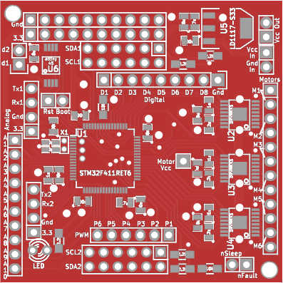
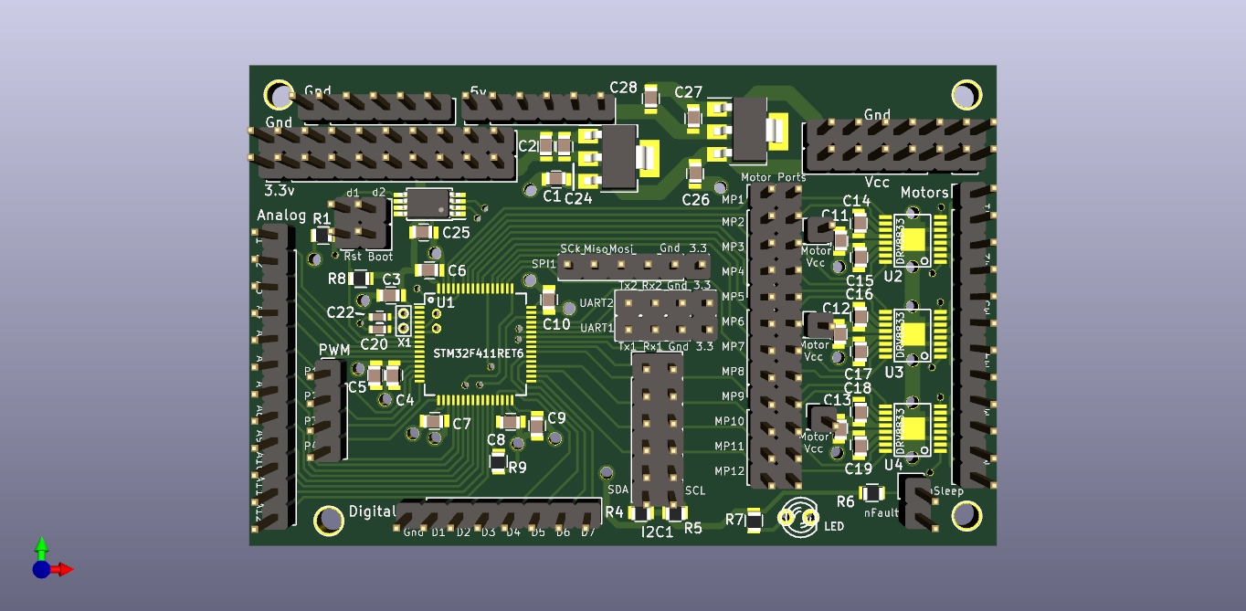
Next over the coarse of testing out the board I found a bunch of idiosyncracies with the STM32 board. For example, you can't use InterruptIn pins with same pin number (no PA_12 and PB_12) at the same time. So I wanted the Digital In pins to have different pin numbers for as many of them as possible up front. Also, I found lots of limitations for PWM pins. There are tons of PWM pins, but sometimes a pin is labeled as a PWM pin and another is labeled as a PWM pin, but really, there are relying on the same underlying counter and so can't be used at the same time. ST has configuration software that was helpful to try to look at all the PWM configurations. I also of course still wanted to use an i2c port, two serial ports, and I decided I wanted to bring out an SPI port. I also decided I wanted access to 5v power since some sensors require it, even though their digital inputs and outputs are 3.3 volt compatible. So to be able to use as many sensors as possible, I decided to put a 5v regulator on the board as well.
I also decided I wanted to put a jumper between the STM32 chip and the DRV8833 motor controller. That way if someone didn't want to use all the motor pins, but wanted PWM pins for something, they could be used. Normally they can just be jumpered, but the jumper can be removed and then the board can have 16 different PWM outputs if needed.
I also wanted to make the board bigger. I found that putting all those jumper wires in the .1" pin headers got a little crazy when I had a complete robot. So I made another revision of the board. Here it is:
Discussions
Become a Hackaday.io Member
Create an account to leave a comment. Already have an account? Log In.