 Tom Quartararo
What is it?
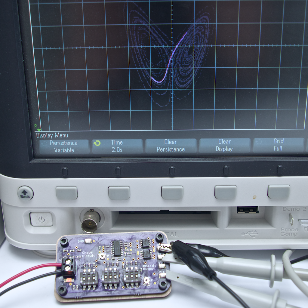
The Chaos Computer is an analog computer that solves the Lorenz Equations to produce beautifully complex waveforms.
The computation of the three non-linear differential equations is performed entirely by analog electronic components; there is no digital computer on the board at all! The circuit is based on the well known implementation by Paul Horowitz with added functionality for easy user interaction.
Check out this brief video showing the Chaos Computer in action!
Chaos theory is the study of dynamic systems that are highly sensitive to initial conditions. This characteristic leads to seemingly random behavior, but in fact the dynamics are perfectly deterministic. There are many real world examples of chaos such as the weather, turbulence, the motion of a double pendulum, irregular heartbeats, and many more. The Wikipedia page on chaos theory has a lot of information if you're interested.
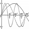
The quintessential chaotic waveform (shown in the image below) resembles a butterfly's wings, which led to the idea of the butterfly effect. I.e. Does the flap of a butterfly’s wings in Brazil set off a tornado in Texas?
Why did I make it?
There are plenty of mechanical devices used to entertain physicists, engineers, and enthusiasts as they contemplate the complexities of the universe. They can watch the balls of a Newton's Cradle exchange momentum, hear the energy being dissipated in an Euler Disk, feel the precession of a gyroscope, etc.
I've designed this Chaos Circuit as a tool to visualize a unique electrical system that is both beautiful and wildly complex. The purpose is to entertain, to provoke thought, to inspire, and to provide a glimpse into nature's complexity.
Who is it for?
For Electrical Engineering Enthusiasts
The Chaos Circuit is a basic analog computer similar to those used to solve complicated equations and models before the digital age. It's awesome to watch incredibly complex dynamics being actively generated by common electrical components. If you're anything like me, you'll find yourself staring at the chaotic waveforms on your oscilloscope while contemplating life and the impact that all of your choices have on the world.
For Educators
Inspiring your students is a priority whether you're teaching high school physics, undergrad engineering, or graduate level mathematics. This circuit illustrates beautiful complexity in nature, coupled with digestible mathematics and simple circuit design. Watching the chaotic output is enough to inspire a student, but you can also dive deeper into the physics and mathematics for more detailed lessons/research.
For Researchers
If anyone has a need for a chaotic output for research purposes, please let me know. I'd be very interested to hearing what you have planned and I'd be happy to help out if I can by modifying the design!
Technical Info
All three outputs of the Lorenz equations (X, Y, and Z) are made available on the circuit (accessed by the test points) so that you can explore all of the waveforms. There are three switches on the board that should all be set to the same value in order to control the time constant of the circuit, which allows the user to slow down the output waveforms for visualization purposes (see video). There are also two potentiometers that are used to control two of the three initial conditions (β and ρ).
The Chaos Computer requires 18 VDC to 30 VDC, and ~15 mA to properly operate. Please note that an isolated power supply should be used to supply power to the Chaos Computer (power supply ground not continuous with Earth ground). This is because the GND on the circuit board is virtual and many oscilloscopes connect the ground probes directly to Earth ground. Using a non-isolated power supply would cause a potentially damaging short that would cause the circuit to malfunction. Reversing the input polarity to the circuit will damage the circuit as well.


 Electroniclovers123
 DIY GUY Chris
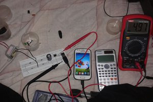
 UTSOURCE
 Kelly Heaton
Seguí las instrucciones y no funciona. Solo salen puntos aleatorios en la pantalla del osciloscopio. Ruego Cambio y / u operativa clara.