 Keith Elliott
With the previous version of the chassis in a working state, I only made two changes for version 0.3. The first change was a major one. As I mentioned previously, I was still a little unhappy with the ground clearance on the last version of the chassis. It ran well on hardwood and tile floors, but tended to get caught on the metal transition strips. It also still had some trouble on the medium-pile carpet in my apartment.
Increasing ground clearance required some significant changes to the chassis design due to the way I was connecting the motor. In my last revision of the chassis (0.1 to 0.2), all I had to do to increase the ground clearance was lower the motor mount so it was closer to the chassis base. However, since I already moved down the motor almost as far as it could go in the last revision, I didn’t have any more room to do the same here! Alternatively I could have just increased the diameter of the wheel, but I was concerned about the motors not having enough torque to move the robot.
The only option left was to no longer directly drive the wheels from the motors and instead use gears. Using gears makes it possible to offset the motor from the base of the chassis but still maintain a strong connection to the wheels. Another benefit is that it’s possible to increase the torque traveling to the wheels by sacrificing speed.
module gear(num_teeth)
{
    num_slices = 20;
    //rotate_angle = ((360 / num_teeth) / 2);
    rotate_angle = 0;
    union()
    {
        for (zScale = [-1, 1])
        {
            scale([1, 1, zScale])
            linear_extrude(height=5, center=false, convexity=10, twist=rotate_angle, slices=(num_slices / 2))
            {
                import (file = str("Gear_", num_teeth, ".dxf"), layer = "", origin = 0);
            }
        }
    }
}
To design the gears, I used a gear generator site to generate a 16-tooth and 8-tooth gear DXF file. Using OpenSCAD’s import function, I imported the DXF files and then projected them linearly to create the 3D gear object.

For the small gear, I subtracted the motor shaft out of the 3D object so it could mounted to the motor.

I merged the large gear with the wheel object so that the wheel could be easily driven. I’m now using a 2mm steel axle to mount the wheel and gear combo.


By slightly repositioning the motor, I was able to move the gears into place so the wheel was properly driven. By mounting the 8-tooth gear to the motor and the 16-tooth gear to the wheel, the wheel now sees a 2x increase in torque at the cost of running at 0.5x the speed. Additionally, with the wheel no longer directly mounted to the motor, I was able move the wheel axle lower. This allowed the wheel diameter to be decreased from 50mm to 40mm while still increasing the overall ground clearance from 7.5mm to 15mm.
I did the above calculations for the force and speed on version 0.2 of the chassis as well as the new force and speed based on the motor specs I pulled from Sparkfun’s version of this motor.
Another part of the chassis that had to change in order to increase ground clearance was the caster. As shown above, version 0.2 had a hole in the chassis to make room for a semi-spherical caster wheel directly mounted to the chassis floor. Doubling the ground clearance, however, would have necessitated the caster, and by extension the hole, increase to a much larger size.

To avoid this, I made the caster entirely separate from the chassis. With two mounts, a 2mm steel axle, and a ellipsoid wheel, the caster no longer needs large holes in the chassis and frees up some internal space. I’m a little concerned that these new casters won’t be able to handle the transitions between carpet and hardwood well, due to their smaller size, but I can always revert to using a hole in the chassis and make them much larger.
The second change I made to the chassis was a minor one. In my mind, the eventual modules that will go with the navigation chassis will be plug and play, meaning no need for screwing or unscrewing them just to swap modules. To accomplish this I knew I needed some sort of mounting method inherent in the 3D design of the chassis.
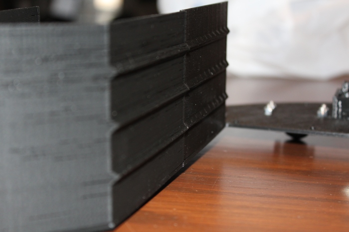
I anticipate some sort of USB or 0.1″ header connector for the method of keeping the modules in place and electrically connected, but for helping to guide the module into I added guide rails to the left and right side of the inside wall of the chassis. These rails will make it easy to properly align the modules and will also keep the module vertically stable.
Discussions
Become a Hackaday.io Member
Create an account to leave a comment. Already have an account? Log In.