-
Screen Capture 002
05/26/2018 at 17:35 • 0 commentsSummary
OK, so I implemented bitmap screen capture. (I also fixed some bugs since last post regarding the Help screen)
Deets
I had recently implemented a Screen Capture feature that captured the TRS-80 screen in text mode. It was a bit of work to get that implemented -- mostly because of infrastructure needs (e.g. generating file names, etc.) -- so I decided to make my life easier then by just doing a text-mode capture. That was easy, since the TRS-80 is a character device, but that mode doesn't capture hypervisor screens, color, or HRG graphics. So doing a bitmap capture was left for a separate activity. Well, I guess now was the time for that. (Oh, along the way I fixed some Help screen bug reported by a user Mikael ☉. Bonnier -- thanks so much for the detailed info; that really makes it easier to fix.)
The TRS-80 is principally a monochrome device, but I support some color boards, and so I did want to be able to have color output. There's a boatload of image formats, but I chose to 'be conservative in what I send', and settled quickly on Windows DIB format as an easy-to-generate-and-widely-accepted format for output.
DIB itself supports many forms of data representation, from monochrome 1-bit-per-pixel to 32-bits-per-pixel. The TRS-80 was natively monochrome, so 1bpp was natural, but I did want to capture my glorious colour extensions, so I wanted a color form. 4bpp made a lot of sense, but then I'd have to fiddle with a color look-up table ('CLUT'/palette) and I just didn't want to fiddle with that, so I decided to unconditionally emit a 24bpp image. This simplified coding, though it made file size much bigger than it strictly needed to be. But who cares?! You've got huge SD to store it! So I carried on with 24bpp in all cases for now.
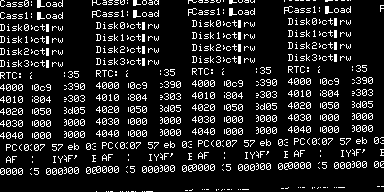
So I started coding. At first I got some images that were plausible, but nonsensical:
![]()
![]()
examining these I could tell that I had flubbed up byte offsets into the screen buffers and some other bugs. Hacking a little further, I got:
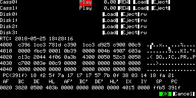
![]()
This looks sensible, but I know it's not right because the colors are wrong. Red and Blue were switched, so I fixed that:
![]()
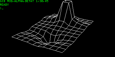
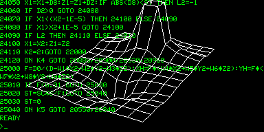
Now,! we're there! I also added in support for the HRG mod, which is technically a separate overlay frame buffer:
![]()
![]()
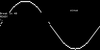
who can forget sinus?
![]()
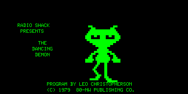
But one thing to note is that these bitmaps are in the native resolution of the TRS-80 -- i.e. 384x192 -- and does not consider that those pixels are not square. For most anticipated uses (e.g. documentation), this is probably fine, but strictly it is not aspect-ratio-correct. I leave it as an exercise for the user to translate in their own programs to do that correction. E.g. here is a native cap:![]()
but here is how it looks on a real screen, as fixed up in Photoshop:
![]()
The needed transformation is simple: 2x horizontal and 3x vertical. I could have done this in the emulator code, but it would have made the file size even bigger, and incurred more CPU, so I left that as a post-production exercise when needed.
The file writing activity seems to take a lot of time. On my UBW32 device, a screen cap takes about 3 sec(?!?!!). So understand that the entire system will be non-responsive during that time.
The default key binding for screen cap is aF8, but it can be altered in the config file, as with the others:
textcap= F8            #capture text screen buffer (ansi)
textcapu= sF8          #capture text screen buffer (unicode)
bmpcap= aF8            #capture bitmap screen buffer
Future
Maybe I'll implement 4-bit indexed color, and 1-bit monochrome formats. This should conserve the I/O bandwidth, making of snappier snaps. The images currently are 200k, but a monochrome would be 9k, and a 4bbp color would be 36k, so there's a real savings. If it turns out to save execution time, then I might also consider correcting the aspect ratio as well (by doubling hres and tripling vres), but this will sextuple back to the 200k file size for the 4bbp images.
-
Screen Capture 001
05/16/2018 at 02:07 • 4 commentsFor a while I've wanted to be able to capture various outputs of the emulator to files for offline use. My prior filesystem corruption problem took precedence over any features that involved writing to the filesystem, but since that got resolved, I feel more free to implement some of these other things.
Most of these capture features are imagined to dump to an automatically named file based on a prefix and sequence number so as to avoid overwriting existing stuff, and keep it ordered. This would require some machinery to be created find the highest sequence number to use within the context of a prefix and for a given directory. Since directory enumeration is rather slow, I wanted to keep a persistent 'index' to give a hint as to where to start the numbering. When a new file names is to be generated, it can start at the value in the 'index', and then bump the number. The index is not required, but it speeds up the generation process by giving a start point that is likely to work, thereby avoiding a bunch of directory traversal. Since I had just finished implementing a config file reader, and which has writing capability, I decided to simply reuse that format for the 'index' file.
Since the TRS-80 display is a character array (as opposed to a pixel array), it is very straightforward to dump the video buffer to a text file. However, there are a couple quirks:
- the TRS-80 (allegedly due to a bug) oftentimes puts chars 0x00-0x1f instead of 0x40-0x5f in the video buffer. Visually, this is not confusing, because they render the same, but from a binary standpoint of course this looks like gibberish. I fixup those character ranges so they read sensibly in a text editor.
- the character array implicitly word-wraps at col 64, so I add linefeeds at the end-of-line so again it looks sane in a text editor.
- the character set of the TRS-80 contains a few unusual characters (e.g. arrows), and then of course all the semi-graphics characters. These aren't going to render at all without some help.
The first two quirks were easily coded around, but for the third I found a font which contains the TRS-80 Model I semi-graphics characters (actually they have the full TRS-80 Model I character set). This is the AnotherMansTreasureMIB64C2X3Y.ttf TrueType font, to be had at:
http://www.kreativekorp.com/software/fonts/trs80.shtml
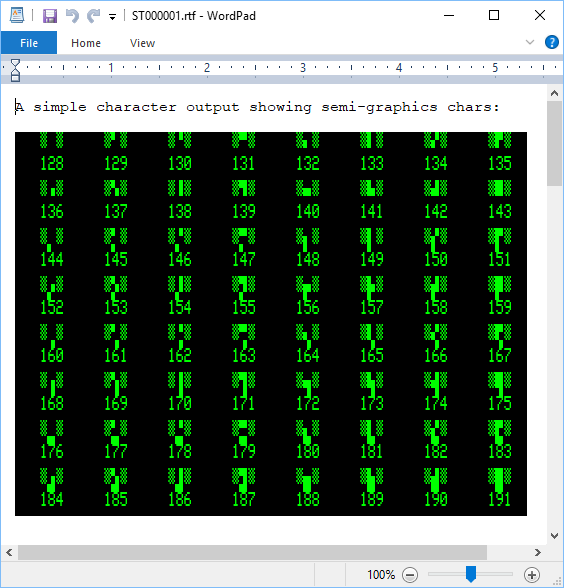
(along with many others).To pull this off, I have another screen capture mode which emits a UCS-2 LE file, and which translates the semi-graphics and special characters into the Unicode range e000-e0ff. So, for those screen captures, you can open them in some editor that allows you to choose the font, and you can now see the TRS-80 screen in it's normal state. Also, since this is text, instead of a bitmap, you can cut-paste the text for your cut-and-pasting pleasure. If your editor has the ability to 'embed fonts' (e.g. Word, LibreOffice), then they can be viewed correctly on other machines even if they don't have the particular font installed.
Here's a few sample captures:
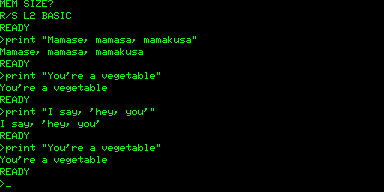
![]()
I have to post these as png because I can't embed the fonts on the web such that plaintext would make sense, but as you can see, I highlighted some of the text (the blue stuff) so that you can more easily see where the character boundaries are located in the textual screen capture. (The green and black obviously is just my specifying the text foreground and background colors, for visual effect).
Anyway, I imagine this will be helpful for when I get around to producing some sexy documentation. If nothing else, I can stop using my phone cam to take pics of the screen for these logs!
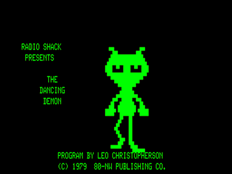
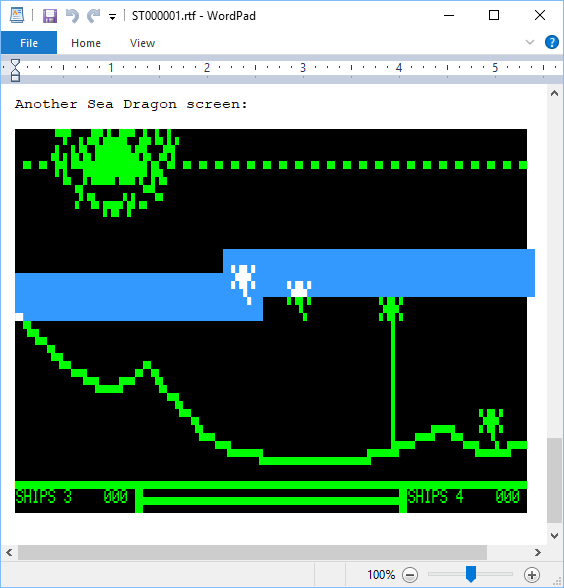
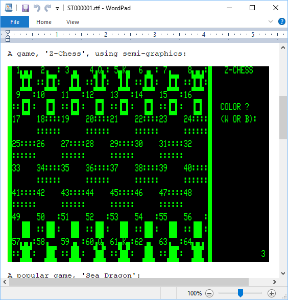
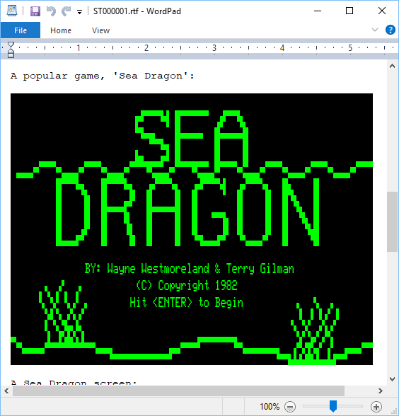
Here are a few others for your retrocomputing viewing pleasure. This is how we did it in the 1970's:
![]()
![]()
![]()
The screen cap function is bound by default to F8 for plaintext, and shift-F8 for unicode translation (for use with the special font). Like the other bindings, you can alter them via config file. Anyway, each time your press F8, it will generate a new sequentially numbered file in the 'scrcap' directory. The naming schema is 'STnnnnnn.TXT', where 'nnnnnn' is the sequence number. (There will be a seq.idx file there as well; ignore it. It is the hint of where to start numbering.)
Later, I'll probably do a bitmap version as well, but that will involve lots more bit-fiddling work than the text mode. This will do for quite a while, but I'm eager to eventually get bitmap working for a variety of reasons, amongst which are that it is the only way to capture the HRG1B output.
-
Config File and Features Controlled Thereby
05/09/2018 at 15:27 • 0 commentsI've long wanted a config file for this project, but never got around to actually implementing one. I decided to give it a go. I found a useful opensource (apache 2) INI file reader project: "minIni", which is designed for embedded (and moreover already had IO bindings to the MDD filesystem library I am using), so this made support much easier with not having to write the parser myself.
My main motivation for the config file was to specify some useful parameters such as:
- auto load a floppy so I don't have to go through the hypervisor every boot
- specify an alternative ROM to use, instead of always Level II BASIC
Other less critical but nifty parameters are:
- control how long the splash screen art is displayed
- support alternative splash screens with ease
- change foreground/background colors on the color board
- alternative key bindings for various hypervisor functions
There is been a placeholder file in the root of the distribution SD card image for some years now, named 'trs80.cfg'. Up to now, it was zero length, but now it has various entries coincidentally set to the baked-in defaults. It should be self-evident how it works, but there are some caveats:
The file contents should be treated as case-sensitive. 'Splash' is not the same as 'splash', and changing it will not result in the desired setting having effect.
Related in particular, is specifying key bindings. This is a limited feature, but you can assign the 'F' keys to various functions listed in the file. They must be named like 'F10', not 'f10'. The keys may be preceded by any of three modifier characters: 's' for shift, 'c' for control, and 'a' for alt. So, 'sF10' means 'shift-F10' and 'scaF9' means 'shift-control-alt-F9'. There are also a couple special keys named: 'Pause', 'SysRq', 'PrtScn'. I don't really anticipate using the keybinding feature that much myself, but I've always been concerned about the 'Pause', 'SysRq', 'PrtScn' buttons, because keyboard manufacturers have a tendency to move those and sometimes make them hard to get to (sometimes requiring yet another 'shift' key). Also, if you have a habit of accidentally hitting the reset button, maybe you want to make that harder by also requiring 'alt' or something on it.
The ROM feature is for loading a custom ROM. There are two baked-in ROM images, referenced by the well-known (and case-sensitive!) name of 'level1' and 'level2'. Otherwise, it is assumed to be a filename of a file in the 'rom' directory of the SD card. Also, a custom ROM cannot easily have cassette traps of the same sorts as I have implemented for 'level2', and plan for 'level1', but if you know your ROM is derived from either the level1 or level2 rom (e.g. System80, or maybe something you hacked yourself), and that the cassette routines are in exactly the same place, then you can 'force=level2' to make those traps be applied, anyway. (Later, I plan to implement some 'syscall'-esque mechanism for truly custom ROMs; e.g. perhaps supporting a CP/M build).
There will be other features added over time that will likely extend the file's content beyond what I have described here. E.g. 'media' only preloads the first disk drive at present, but I'll probably extend that for all four, and also the two tape decks.
-
Minor Cassette Enhancement
05/06/2018 at 14:46 • 0 commentsThe cassette I/O functionality has, since the beginning, been realized with traps in the ROM routines that are serviced on the host side of the emulator. This saved me the trouble of trying to emulate the pulses with the correct timing for the Z-80 code, and had the side benefit of being some 160x faster than native cassette.
A user had reported that EDTASM did not seem to do anything useful when trying to save and load programs from the cassette, and it was hypothesized that it might be doing it's own I/O directly, without using the ROM routines (and thereby my traps did no good). A quick disassembly verified that this was the case. In fact, it also has it's own copies of the keyboard, video, and printer device drivers, and it doesn't use any ROM routines!
Upon closer inspection of the disassembly, I noticed that the routines were very similar to the same ones in ROM. At a source level, they were identical except for a very few omissions that were pertinent to the BASIC environment. One would think this is wasteful, since they are right there in the ROM, but it occurred to me that EDTASM may have been produced /before/ the ROM was created, and that the device drivers may have been platform-specific code given to Microsoft to integrate into their BASIC codebase to result in what became "Level II BASIC".
In any event, because the code was so similar, it occurred to me that it might be possible to simply patch EDTASM to forward the key parts of the cassette implementation to the ROM, and then it would benefit from the existing traps.
This plan was underway until I noticed a snag: while at a source level, the code is identical, the machine code is not. In particular, there is a state variable stored in RAM that is placed differently between the EDTASM and the ROM. (a software copy of port 0xff). For most of the cassette implementation, this doesn't matter, but it did for the cassette on/off, and for the video functions which are also on port 0xff.
I could have said 'Hail, Mary', and just hoped for the best -- I suspect it would have been OK -- but then again it might not have. After a while, it dawned on me that I could patch most of the code -- the data I/O, and leave the cassette on/off code unmodified, and avoid there being changed assumptions about the location of the state variable (in ROM, at 4028, in EDTASM, at 403d).
In the emulator, I had already virtualized the cassette relay bit, and also the drive select latch at 37e4, but I had never provided implementation. So, this update provides implementation for those two things, allowing me to make my patched EDTASM.
I tested it out by entering a small program (the example from the manual), saving the source to tape, clearing memory, loading the source back in, assembling and saving the binary to another tape. The resulting tape images looked fine, so I conclude that works as-expected.
I placed my modified EDTASM in the SD image under the name 'edtasm-p.cas' ('p' for 'patched'). You load it just as you would the original. It is derived from version 1.2.
-
Orchestra 80/85 Support
04/28/2018 at 01:49 • 2 commentsThe PWM has been in-place for quite some time (and is used for the 'cassette sound' feature that many games use), but I had never gotten around to implementing the Orchestra 80 support, even though it should be simple. Part of the reason was that I didn't have any software or files for it, and part was just that I had forgotten about it.
Since I had a little time today, I decided to do a little research on the web, and found a copy of the ORCH85/CMD and a few music files. Also, I found a copy of the manual for Orch 80.
I have no idea how to run this program, and it seems I would need a minor in musicology to understand a lot of the stuff in the transcription setting, but I think I can manage loading a file and playing it. It turns out there is a command, 'GET', which loads, 'scores', and plays the music files, so that is good enough for my testing, I think.
The hardware was trivially simple: two I/O ports (0xb9 and 0xb5 -- seems unusual) write an 8-bit sample to a DAC for left and right channels. The rest is all done in software. So I coded a connection from those I/O ports to the existing PWM.
For the Olimex board, it required a little thinking: that board only has one PWM channel. I decided to simply average the two channels' values in that case. Since the channels are written one at a time, I needed to store the last written value for each channel, and average those to create the effective setting for the PWM.
The initial sound output sounded pretty bad, but was recognizable. Could it have really been this bad back in the day? Or was it my crappy amp and speaker (a couple bucks on ebay based on an LM386, and an equally cheap speaker element probably intended for a toy)? Or was it the output filter on the boards? Maybe a combination of all these things?
I figured it would be best to start, if possible, with just one note. Ideally generating a sine wave, but I couldn't figure out how to get that fancy. But I did figure out that I could enter the music of 'W0' which meant 'a whole note of middle C'. Then I captured that signal. It looked like crap (sorry, I should have captured the scope trace, but I didn't), so there definitely was a weird signal going into the audio amp.
I added a little testing code to write all the values sent to a file, so I could analyse the data stream. The data at first glance did seem to look like it probably would have generated that waveform, so I started to guess that it is a signed/unsigned problem.
I loaded the file into a waveform editor as a 'raw' file, and started with 'unsigned' (since that is the way I was interpreting it), and visually the waveform did look like the scope trace. I re-imported it as 'signed' and then it looked much more sane (with an apparent fundamental, and some lower amplitude harmonics riding on top of that).
So, changing to unsigned is just a simple matter of an offset of 128, and that seemed to do the trick. The scope trace looked sane, and the output was improved. I wouldn't go so far as to say it sounds great, but it was not as bad as it was. Maybe it would sound even better with a better amp, speaker, and filter than I am using.
The copy of the orch85 software I have on-hand is for disk, so I created a floppy image 'orch85.dmk' which has that, and some music files. If you want to try the software, know that you need to specify some parameters on startup:
'speedup' indicates that a speedup modification was installed on the TRS-80. Answer 'no' to this. (much as I would like to speedup, the 80 MHz PIC32MX doesn't have enough free cycles to do it).
Then it asks for number of voices 3/4/5. I suggest picking '4' since that is the default and seems to be what most files are configured for.
Lastly, it asks if you want to 'save program'. This creates a copy of orch85/cmd that has the above options burned in. It seems to be doing a bit more than simply stamping in the parameters, because the binary diff is significant. If you 'save program' you will be prompted for the new program name. I called mine 'ORCH4V' to indicate it is configured for four voices.
When running the program, you can issue 'DIR' to list the ORC files on the disk. Then you can either do the sequence of READ fname, SCORE, PLAY or your can do all three with the GET command.
Beyond that little walkthrough, you'll have to read the manual for yourself, which I included in the 'manuals' section of the SD card zip file.
-
Bugthzs 002
04/26/2018 at 00:01 • 0 commentsThere has been a known issue for quite a while that cassette writes can cause filesystem corruption on the SD card. Usually, I approach bugs from a 'surely it's something I did' standpoint (and in truth, I prefer if it's something I did, because then I'm in a position to fix it), but sometimes it's not, and you have to be prepared that you might have to prove it one way or the other.
Long story short: there appears to be a bug in the Microchip MDD library specifically when opening a file in the "r+" mode, and when the file length is 0. If you do, you will incur file system corruption upon subsequent writing. If the file is of non-zero length, then "r+" works as expected (and thank goodness for that).
I am using the latest libraries, to wit 1.4.4, which interestingly contains a fix to "r+" mode (though apparently unrelated to this issue).
Anyway, because of the nature of the problem (only with 0 length files), what I do is translate "r+" to "w+" when the file length is zero. This incurs some otherwise unnecessary file operations on opening, and has some consequences regarding position in the filesystem and timestamps (because in "w+" mode the file is deleted and then re-created), but I think this is minor enough to disregard - especially relative to alternative: filesystem corruption.
So hopefully this is the end of this issue. It was a long and painful journey.
-
HRG1B Support
04/23/2018 at 02:04 • 14 commentsThere were a very few 'high-resolution' modifications available for the TRS-80 Model I. Some were downright weird, such as the 80-GRAPHIX board, which worked though the character generator. One of the more sane ones was the HRG1B, which was produced in The Netherlands . It worked by or'ing in video dots from a parallel memory buffer, and this buffer was sized at the TRS-80's native resolution of 384x192.
This was on my 'to-do- list of things to implement, but [harald-w-fischer], actually had one of these on-hand from time long past. He also had manuals, some of the stock software, and some extensions he his self wrote! This was needed to be able to faithfully reproduce the behaviour, and some of my initial assumptions were proven false by it.
Since my emulator already has framebuffer(s) at the native resolution, my thinking was that this would be easy to implement. However, I was mistaken. It was mostly easy to implement, but there were several challenges.
- merging
At first I planned to directly set bits into the 'master' frame buffer(s) when writes to the HRG1B happened, but after disassembling the 'driver', it was clear this wouldn't work. For one, there needs to be supported reads from the HRG buffer that don't reflect merging, so a separate backing buffer would be needed to do this. Second, the HRG supports a distinct on/off capability, so again the separate buffer would be needed, but also the case of when to merge the buffers arises. Lastly, the computational overhead of doing the merging on-demand caused overload and required some legerdemain. - memory
Whereas the Olimex Duinomite-Mini board (which Harald is using) can easily accommodate the 9K frame buffer required, my color UBW32-based board is just too memory constrained. The color boards already have 3 frame buffers, and this makes a fourth. Initial experiments were done on the Olimex, where the memory was not a problem, but I really wanted it to work on color, too.
The first experiment I tried was to just see if there would be enough time to merge the image during the vertical blanking interval. Since I am upscaling the TRS-80 native 384x192 to 768x576, and then padding with blanking around to get to 800x600, there is a bunch of vertical retrace time where I could do the buffer merging. Maybe the processor is fast enough to do it on-the-fly?
Well, no, it's not. The buffers are small (9K), and the operation is simple (or'ing on the hi-res buffer onto the main buffer), and the operation is done on a word basis on word-aligned quantities, but it's not enough. The major problem is that the vertical blanking interval is driven in software by a state machine that is in turn driven by an Interrupt Service Routine (ISR) at the horizontal line frequency. The vertical state machine is mostly line counters for the vertical 'front porch', sync period, and 'back porch'. So, although the vertical blanking period is a long time in toto, it is comprised of a bunch of short times. The naive implementation requires all the work to be done actually during a horizontal line period. In my first iteration, I wound up dividing the work into chunklettes, spreading out between several horizontal line intervals. I generated a test pattern, and this scheme appeared to work.
Having received the HRG1B driver and sample apps from Harald, I naturally had to immediately disassemble them. I have to say, the driver is a little piece of art. The goal is to extend the existing BASIC with some new keywords, and what they chose to do was hook a routine that is sometimes used during the basic execution process (it is rst10h, used to skip whitespace to the next token). The hook observes if it is coming from the interesting places, and either leaves if not, or carries on with it's shenanigans. The shenanigans consist of looking for a '#', which is the prefix for the HRG extensions. As implemented, the HRG repurposes the existing BASIC keywords of: SET, RESET, POINT, OPEN, CLOSE, LINE, CLS, CLEAR. If those are prefixed with '#', then the HRG driver performs it's alternative implementation, parsing a parameter list, and executing functionality. When it has finished consuming as much as it can, it then returns to the regular routine. So, in effect, the HRG commands act like whitespace to the command interpreter, and the driver consumes and executes those commands. By reusing the existing BASIC tokens, the parsing is simplified, since those have been converted to a one-byte code, but this is not required. In fact, Harald had made his own extension to the driver which introduced a new command 'CIRCLE' which would necessitate a full string compare of 'circle' since that is not a standard token. After my fun with disassembly, I returned to the task at-hand.
The video code was quite a mess because it is a legacy of the Maximite code that Geoff Graham had given me permission to use, and upon which had I mercilessly hacked. In that project, there were a bunch of different video modes supported, and also composite (CVBS) video -- none of which were relevant here, and had been cut out and replaced with the single 800x600 mode with funky pixel doubling and line tripling needed for the TRS80. Since I was about to add more complexity, I decided to take a couple days and clean that code up for intelligibility. Mostly this came in the form of lucid comments, and explicit computation of timing parameters from the specs. Some came from discarding vestiges of features no longer realized (headless, TFT LCD, etc). There's more to do, but that module is now a little bit tidier.
I still felt bad about merging the entire frame buffer each vertical retrace time, and thought about optimising this to only be done when output (either to the main screen buffer, or the HRG buffer), though this would be major surgery. However, my desire for color support (or at least thoroughly understanding the limitations) drew me in a different direction.
So, a component of the system, the 'hypervisor' (borrowing jargon from the virtual machine industry) is realized with a 'dialog manager' facility that I created. This dialog manager is similar to the way things are done in Windows, and you create a screen with a 'template' that specifies the location of 'controls' that are things like static text, buttons, check boxes, list boxes, edit fields. You provide a 'dialog procedure' that handles 'messages' sent from the controls when things happen. I implemented a text version of all those controls that works on the TRS80 screen. It's a development boon to have this facility, but I know that it's heavy on the use of malloc(). But how heavy is heavy? The malloc() implementation in the standard library does not expose methods to let you know how much heap you've used, or do a 'heapwalk' to inspect all the allocated objects. This is something I've long wanted, and now push came to shove.
So, I implemented my own heap manager. It implements malloc(), free(), realloc(), and has some diagnostic features where you can inquire how much free space there is, and also do a heapwalk though all blocks (allocated and unallocated) to scrutinize heap use closely. There's some magic in the gcc linker that can be used to 'wrap' a function by giving it an alternative name. This is particularly useful, because other things that have already been compiled use malloc(), and I need them to be redirected to my malloc() -- not the one in the standard library. This is a handy feature, but gcc specific. Anyway, I discovered that the dialog manager uses a lot of memory. Something like 12 KiB for the first hepervisor dialog. A full video screen is 1 KiB, so it's certainly not just the content. What could be taking up all that space?
Looking at the code, I found one culprit: v-tables. The dialog system is designed in a object-oriented manner, as might be expected, but I had put the vtable of the controls as members of the objects, rather than a single pointer to a const table (that is in ROM). That was foolish of me to start with -- what was I thinking -- and a bit painful to fix, but that gave me about 5K back right away. Half a frame screen buffer! There's more improvements I think I can make there (e.g. copy-on-write for text values -- why copy it to RAM if it never changes), but I'm past my RAM crisis for color support for the moment.
Returning to the HRG implementation, I have a new new idea: merge on a raster-by-raster basis. I.e., there is no master buffer, but rather there is the TRS-80 buffer, the HRG buffer, and just a single raster line buffer for the current raster line. Only a single line needs to be merged (prior to display), and no sophisticated (and bug-prone) code for 'optimized' merging needs to be implemented, and the implementation of HRG on/off becomes trivial (you either merge TRS80 and HRG, or just copy TRS80). But... it all needs to be completed during a few clock cycles at the beginning of the horizontal interrupt period.
At first, this seems plausible, because a horizontal line is just 12 words long. But there's still not a lot of time to dawdle, because there are just 256 CPU clocks from the moment that the interrupt is stimulated (by timer 3 maximum count being reached) before raster data is needed to be available for shifting out via SPI and DMA. Some of those cycles have to go into state machine logic and also to setting up the peripherals before the trigger comes (via output comparator that ends the horizontal sync pulse). 'Time' will tell.
As before, I have enough time to keep up on the monochrome Olimex board, but it's not quite enough for color. Looking at the screen in the failing color mode, it looks like it is almost there, but just shy of having enough time. sigh. Maybe some assembler will help. At the least, I unrolled the loops, since it's just 12 sequential 'x++ = y++ | z++' operations.
As a side benefit of this approach, a thing that had vexed me for some time is effectively solved: the hardware is such that the rising edge of the horizontal sync pulse is what triggers the SPI/DMA to start shifting out dots. The problem is that this is not per-spec. The spec requires some 'horizontal sync back porch', which is some quite time before the pixel data comes. In CVBS signals, this is where the color burst goes, but in VGA it's just a quiet time. This quiet time is simulated by left-padding the horizontal lines in the screen buffers with dummy bytes. This has always irritated me, because that space adds up: 192*4 = 768 bytes per color plane, == 3072 bytes for color with HRGB. I want that 3K back! But by doing this raster line merging, only the raster buffer needs to have the padding, so that's a 3K savings in RAM. It's the little things in life....
Anyway, one morning I awoke with another distributed work solution to my color problem: only merge half the raster line, then setup SPI/DMA, then merge the other half. By only merging half, that gives enough time to setup SPI/DMA before the trigger comes in from the output comparator that starts shifting out dots, while at the same time providing enough work for the SPI/DMA to keep them busy while we finish up the second half of the raster line. This wound up to be not too tricky to implement, and worked fine for both monochrome and color.
Now, I had to finish the hardware emulation of the API used to interface with the HRG board. As mentioned Harald Fischer had a physical unit, and also he had the driver software. So I disassembled it. He also had some scans of the manual, which he sent as well. I'm so glad he did, because the API is a bit byzantine. First, the addressing scheme is a 16-bit quantity, but it's not linear. Rather, the 16-bit 'address' is actually a bitfield of character row, column, and raster line within the character cell. Second, each memory location is 6-bits, not 8. In retrospect, I'm not so surprised - the board is implemented with SSI TTL and the 6 bits reflects the 6 pixel wide characters on the TRS-80, and I'm sure that it was convenient from the standpoint of tapping signal lines to keep that structure (yes; many hardware upgrades in those days required cutting traces and soldering. Plug-in cards are for babies!). But, I now have to emulate that addressing scenario and do a bunch of masking and bit-shifting. My favorite.
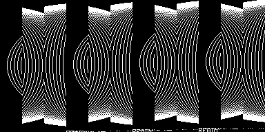
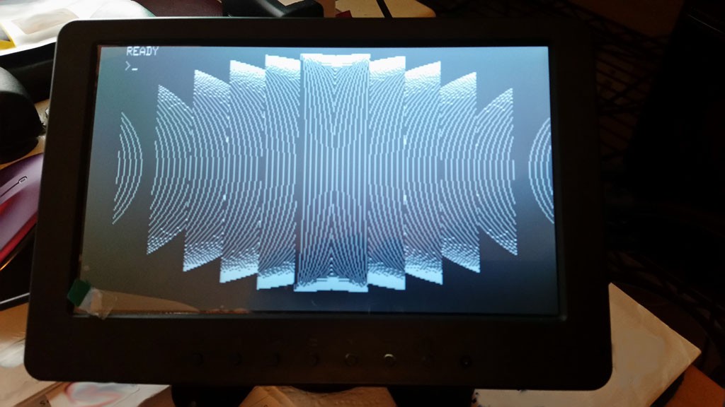
Knowing that this would be a brain-melter, I put it off until I had a morning to come into it fresh, ready to formulate test cases for boundary conditions, and code up a bunch of bit masking and shifting, dealing with 6-bit-bytes that may or may not straddle a 32-bit word boundary. About 4 hours later, I had gotten it wired in, and ran a test program that came with the board (again, thanks to Harald's provision). This is a program called 'elips', which draws a series of concentric ellipses with ever widening minor axes.
![]()
Hmm. Somethings not quite right. Oh! The SPI on the PIC32 is MSB first, but the HRG1B is LSB first. I forgot this. When I was doing the character generator ROM, I preconditioned that data to be pre-reversed to accommodate. However, in this case I've got to do the bit reversal in software and then also map in reverse into the words of the raster line. sigh; more brain-melting.
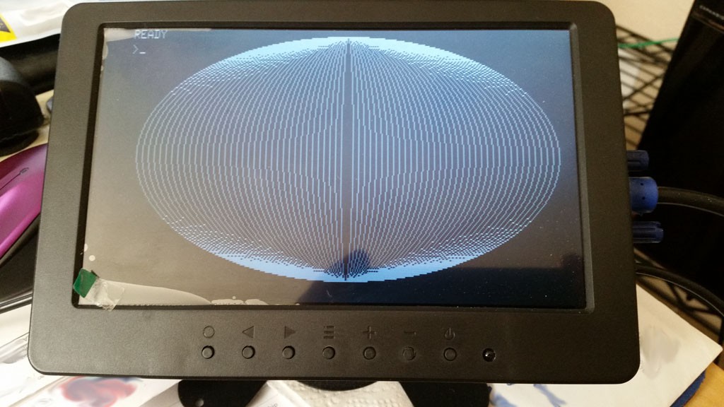
After about three more hours I had managed to get the bit reversals, shifts, and masks right.
![]()
9 minutes, 42 seconds. 36 ellipses.
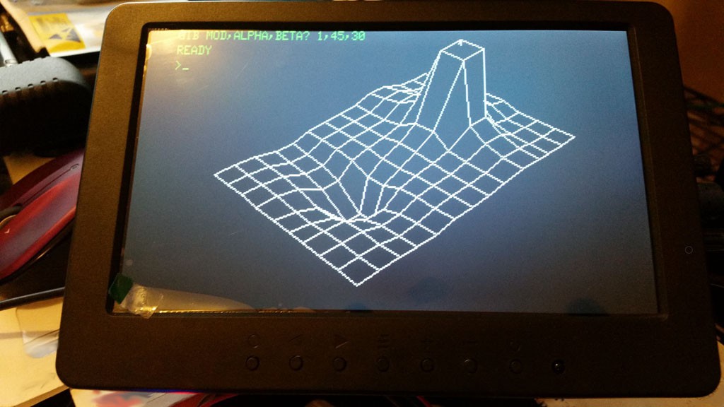
And for fun, once I figured out meaningful parameter parameters:
![]()
Hope you've got a little time for that one; something like 15 minutes. (-1, 45, 30 turns off hidden line removal, and takes about a third the time)
- merging
-
Bugthzs 001
03/31/2018 at 03:01 • 0 commentsOK, after quite some time of quiescence on this project, some bugs were brought to my attention.
First, rather embarrassingly, a character generator bug resulted in to graphics characters being incorrectly rendered. [harald-w-fischer] had pointed this out over a year ago, but due to ever-present-and-multitudinous weirdness in this platform, I did not receive notification of his posting until recently, when [Mikael ?. Bonnier] observed similar consequences. Thank you guys, and apologies for not having corrected it until now. (And extra special thanks to Harald for digging into the code to effect the fix himself!) I also reflected this fix into the 'wide character' font, and along the way noticed that character 0x7f didn't look quite right, and fixed that too.
Second, and perhaps more embarrassingly, Mikael discovered that saving to cassette tapes did not function. I guess I have never actually tried to save to a cassette, because Lo! and Behold! it is true it did not work. This ultimately was due to a trivial logic error of inversion: the cassette write routine is meant to verify that a cassette is selected, before writing data. In fact, the opposite was done, and if a cassette was selected, it would abort writing. Heaven's knows what would have happened if you tried to save with no cassette selected (Heavens does know: crashy-crashy). Anyway, that logic error is corrected.
So those two bugs are fixed, and I have updated the 'files' section with images I have tested. I left previous image in place just in case this for some reason doesn't work, but I'm quite confident of the fixes.
Lastly, Harald has a rare-ish piece of hardware: a modded Model I with the HRG1B board. There were a very few 'high resolution' boards for the Model I back in the day, but most were farcically unusable. The HRG1B seems to me to be the only sensible implementation, which is a dot addressable pixel array (of the impressive 384x192 resolution!) that overlays the native resolution. I can only guess as to how much such a thing cost back then. Anyway, I've never found any documentation on such, much less software, but Harald has a vintage copy of the graphics kernel driver and some sample programs, so I'm now eager to implement that support. I haven't spent much time on the software, but a cursory disassembly of the kernel and a glance at the BASIC source looks like might be some interesting things are in there!
-
USB to PS/2 keyboard adapter improvement
09/22/2016 at 19:57 • 0 commentsPS/2 keyboards are getting rarer, and I knew I had successfully used one of the USB to PS/2 adapters before, but for some reason it no longer worked. So, out came the oscilloscope again.
What I found was that the keyboard (or probably it was the adapter) was continually sending the 0xaa value every 600 ms. That value, 0xaa, is the 'Basic Assurance Test' (BAT), meaning that the keyboard passed the power-on self-test. But why was it sending it repeatedly, and not sending any key codes?
I hazarded a guess that it want some interaction from the host, so I sent the 'set LEDs' code upon reception of the BAT. Doing so seemed to take the adapter out of whatever state it was in, and restored relaying of keycodes from the USB keyboard.
While I had my probe wires soldered to the board, I tried a USB wireless keyboard through the adapter. This did not work. Unlike as with the wired USB keyboard, in this case the adapter simply remained silent.
So, I've checked all that in, and you should now be OK to use one of those adapters with the emulator, with a more modern USB (wired) keyboard if you don't have a native PS/2 one on-hand.
-
2nd Platform Support -- Olimex board
09/20/2016 at 20:42 • 0 comments"...O frabjous day! Callooh! Callay!' He chortled in his joy."
Today I finished porting the code to the Olimex Duinomite Mini board, so now you can have your emulator for about $25 USD (for what we paid upwards of a couple grand in the day), and soooo much more reliable. (and no soldering for the Olimex board).
I have tested video, keyboard, SD card (cassette/floppy), and sound. I believe the porting task to be complete.
I have updated the project-related file to now contain both firmware images, one for the UBW32 (based) board, and also the aforementioned Olimex board.
The Olimex board does imply some limitations:
- it is a monochrome only VGA board. Since the original TRS-80 was monochrome, this isn't the end of the world, but you won't be able to simulate the green screen filter. Also, pay a little closer attention to the controls states in the 'hypervisor' since you won't have color cues to guide you. But I think the reverse video does an adequate job of letting you know what control has the focus.
- this board does not have a battery-backed RTC, alas. I haven't really been using that feature yet, anyway, since OSs needed to be patched to use the aftermarket RTC's of those days. I guess it would affect the file modification date on the SD card, but who cares?
- this board only has one PWM channel, so you won't get Orchestra-85 stereo. I arbitrarily selected 'right' as the available channel. The cassette-based sound is directed there, so you can play all the games just fine. Do note that the PWM channel on this board is not capacitively coupled.
- this board can be run from USB power, or from adapter by selecting a jumper near the jack. YOU MUST USE ONLY 5V REGULATED ADAPTER with the Olimex board. Not even 7v. Get a cheap 5V switcher wall wart off ebay or something. There is a zener on the board to help a little with booboos, but mr zener gets pretty hot and cranky when he's made to work.
I guess what I have left is serial emulation, maybe hard disk, maybe some sort of printer, and maybe a 3D printed case might be nifty.
TRS-80 Model 1 on a PIC32
TRS-80 Model I emulated on a PIC32MX processor; VGA, PS/2, and SD for tape and disk images. Oh, and glourious cassette sound.
 ziggurat29