 Bill Peterson
I soldered the USB jacks for power and MIDI controller onto my perma-proto hat. I shelled out $6 for one of these because it's got pads on both sides - needed so I can solder the jacks on top where they'll fit - and it's sturdy and has mounting holes to hold everything together. First thing I did, of course, was break it. I drilled holes for the little anchor tabs on the USB jacks, and the first hole in the ground rail next to the 3.3V rail is where the trace from the header is connected. No biggie, since there's another ground rail by the 5.5V rail.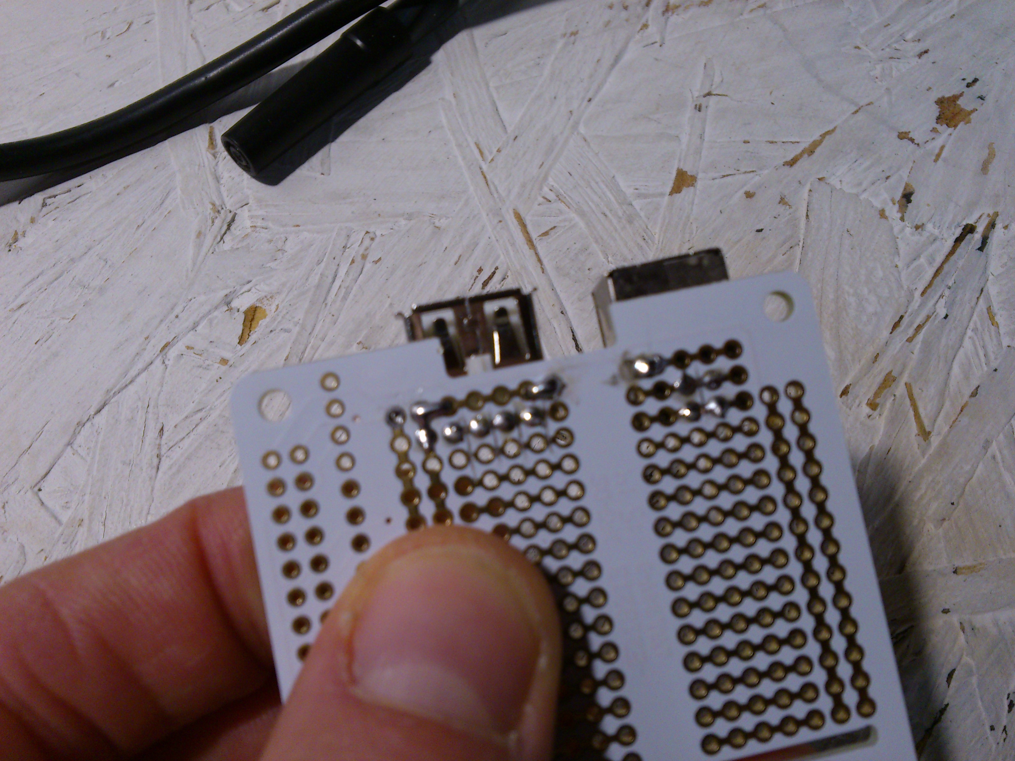
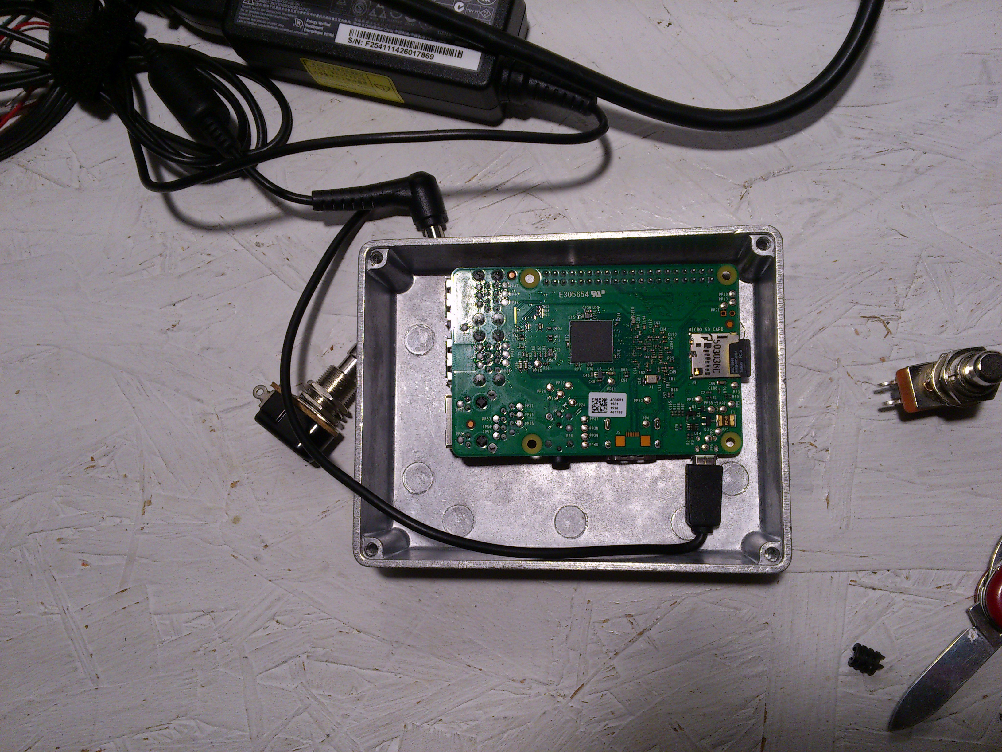
Fitting things into this box is going to be tricky. I'd hoped to chop the end off a micro-USB cable and wire it to the B-jack to get power to the Pi, but it's a tight fit even with some of the plug sliced away (the laptop PSU is just photobombing - not part of the project).
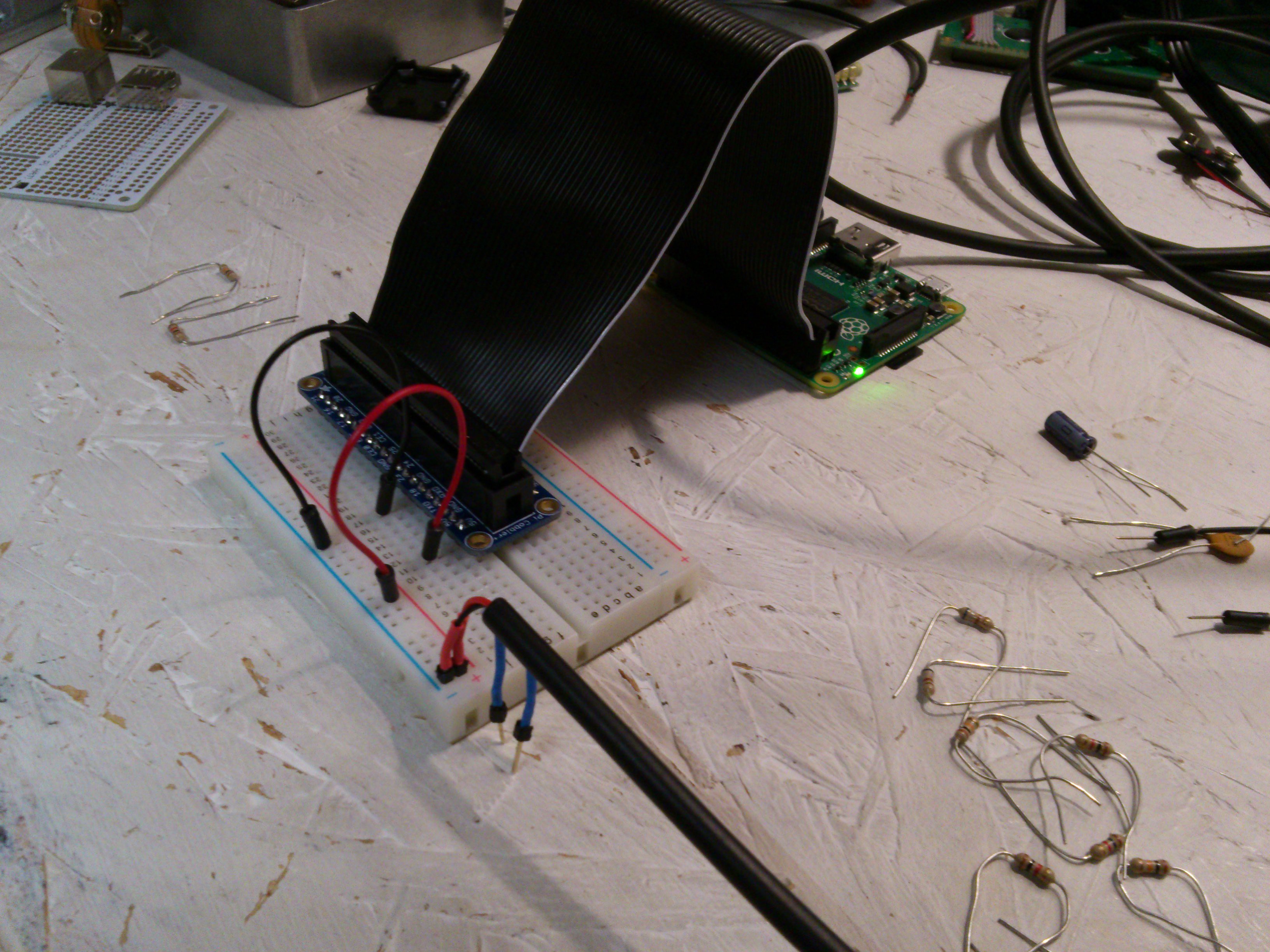
I put the voltmeter on the pins and saw that the voltage was fluctuating rapidly between a few tenths of a volt and maybe 4.5 volts. I imagine what's happening is that the Pi is beginning its boot sequence, and the switching voltage regulator in the 5V adapter is not keeping up with the current demands. The Pi decides something is wrong and shuts down. Then, current from the adapter ramps up and process repeats. The electronics in a console cable must be better able to handle this.
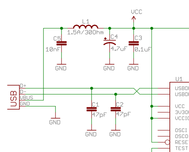
I took a look at the schematic for an FTDI cable and saw all those filtering capacitors sitting on the 5V line - maybe they filter out those rapid changes in current demand. I tried to copy it on proto (I know a coil of wire does not a ferrite bead make, but EMI shouldn't be a huge problem here).
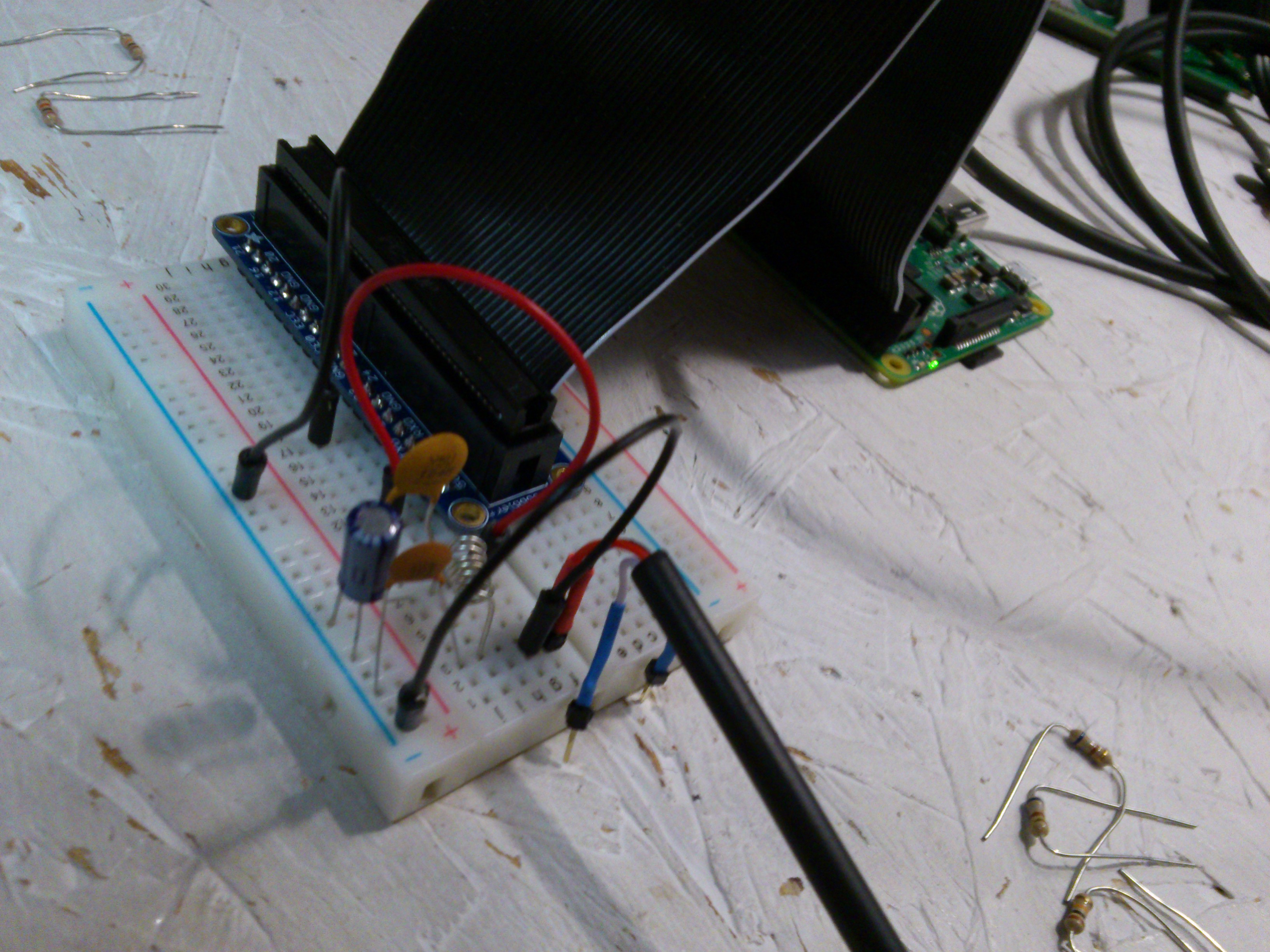
I was able to pop the casing off the microUSB cable plug, so I should be able to go that route after covering it with some shrink tubing. Probably the safer option, but I would like to know what makes my FTDI cable so special.
Discussions
Become a Hackaday.io Member
Create an account to leave a comment. Already have an account? Log In.