So basically what I did is I took a lightbulb for car brakelights which contains two independent filaments in one bulb (one is for the normal tail light and the second brighter one lights up when you brake) and I burnt the less bright one by connecting it to some powerful 50V supply.
What I wanted to experiment with is, seeing if I could measure a noticeable diode current trough the now disconnected filament connection (anode) and the burning filament (cathode).
In fact, as I tried it I first could not measure anything because the current was presumably too small for the multimeter, so I tried a load resistors of 1MΩ and measured around 30mV across it which means that a current of 30µA flowing.
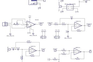
The next thing I did is I wrapped some aluminium foil around the glassbulb as a "grid" to see if I could turn it into a triode. I could not use the other connection of the burnt filament for this, because it is internally connected to the other filament. As I tried applying different voltages to the grid and measured the voltage across the load resistor I could not measure significant changes with the multimeter. So I quickly wired an op-amp amplifier circuit on the breadboard, used a dev-board of mine ( an USB-oscilloscope-signal generator thingy ) to apply a sinus-signal (0..-10V) to the grid and measured the amplified signal on the oscilloscope. Alas I still could not recognize no sinus on the output, so I wired up a second amplifier stage so I had a 80dB amplification. At such a high amplification the signal i saw was really noisy but I could see a something of a regular pattern. At last I threw a 1kHZ low-pass filter in the mix and finally I could see the output signal.
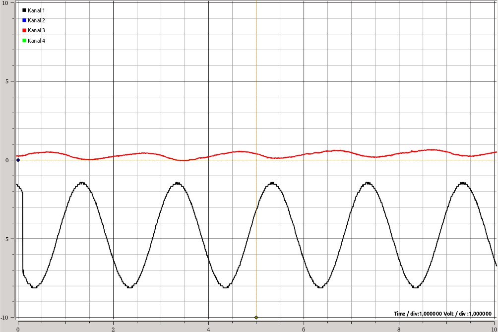
(the input signal is the black one and the output the red one, 1 unit is 1V)
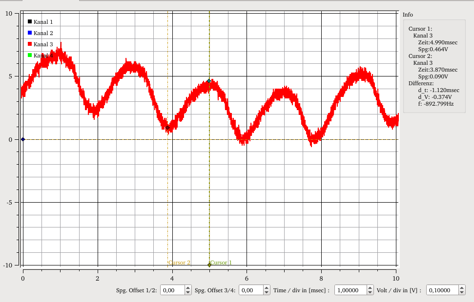
(the red signal is the output signal, here 1 unit is 100mV)
The output signals amplitude was around 370mV peak-to-peak which means that with the input signal being 10V peak-to-peak and considering the signal was amplified 10000x, my triode itself has an "amplification" of -108dB !
[Edit]
As a useful commentary pointed out, I forgot to measure the signal without the heater being turned on to see if the measured effect was not due to unwanted capacities or inductivities. (It really is a shame I did not think about it myself!)
I tried it and indeed even without the heating you can see the signal on the output so a great portion of it is due to capacitive or inductive coupling. But when I connect the heater I can see the signal amplitude increasing a bit so the grid does work, but its effect is even smaller than I first thought.
So as we can see it has no practical use, but it was sure nice to experiment with!
The reasons why the anode current and the amplification were so small are (I guess) the following:
- I used an anode voltage of 10V whereas in normal tube circuits voltages >100V are used. This increases the anode current
- The grid should be between the anode and the cathode to better reflect the electrons and prevent them from flowing to the anode whereas in my experiment the grid was outside and quite distant. This decreases the influence of the grid voltage on the anode current and therefore the amplification.
- Light bulbs today are filled with inert gas whereas vacuum tubes as the name says do not

 Jesse
Jesse
 Manuel Tosone
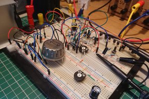
 Lukas Koch aka Ast
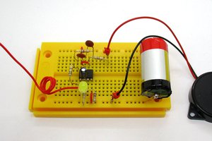
 Burkhard Kainka
Nice experiment, did something similar a few year back with a florescent tube and made something similar to a thyratron yalve relaxation oscillator. Except the outside foil tape was the pinch grid - http://www.hardhack.org.au/oscillate_fluorescent