 Benchoff
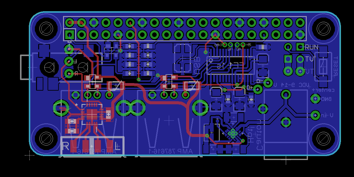
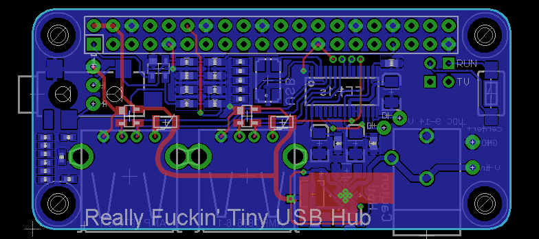
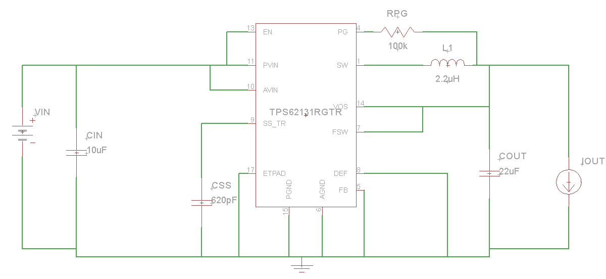
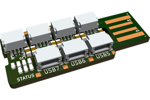
This USB hub is meant to stack on the bottom of the Pi Zero. It provides 3 USB ports, audio output, and a power supply from a 12V wall wart.
This is not a product and it never will be; it's something I've designed to be as small and as capable as possible. This means hot glue and random wires soldered everywhere. These wires will be hidden, yes, but this is not a 'professional' solution. It's a solution that's as small and as capable as possible, while still doing everything I want it to do.


 rbtsco
 Thomas
 Jacob Daniels
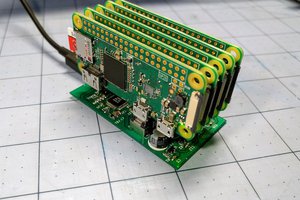
 ajlitt
sweet, the audio out is nice. May have to build one up this will be great for puredata on my pi zero