 edge9001
* inside a phone wire there are typically 4 colored wires red, green, black, and yellow. for this project there are three circuits, a red/green circuit, a red/black circuit, and a red/yellow circuit.
* the red/green combination is the intercom itself. the green wire is run from on phone to the next with no other connections.
the red with is where the 12v dc connection is made.
* next is the red/black circuit. this circuit has a switch on one end and a 12v light on the other.
* the red/yellow circuit is done the same except the the location of the light and switch are reversed.
this will allow signaling between the 2 phones. the idea is to pick up your phone, and flip the switch (the other side of this will see the light lit up and know this means someone wants to talk). and listen for the other end to answer. once they do turn off your switch and carry on you conversation.
this design over comes the signaling issue as well as the battery powered issue. It also gives a work around on the issue of both phones needing to be off the hook for the system to get power. the phones themselves still require this, but the signal lights do not.

 Dr. Cockroach
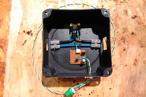
 Szabolcs Lőrincz
 carbono.silício
 Silícios Lab