 Arduino Enigma
By now the Black and White V2 PCBs have arrived. They are certainly slimmer than the V1 Green PCBs,
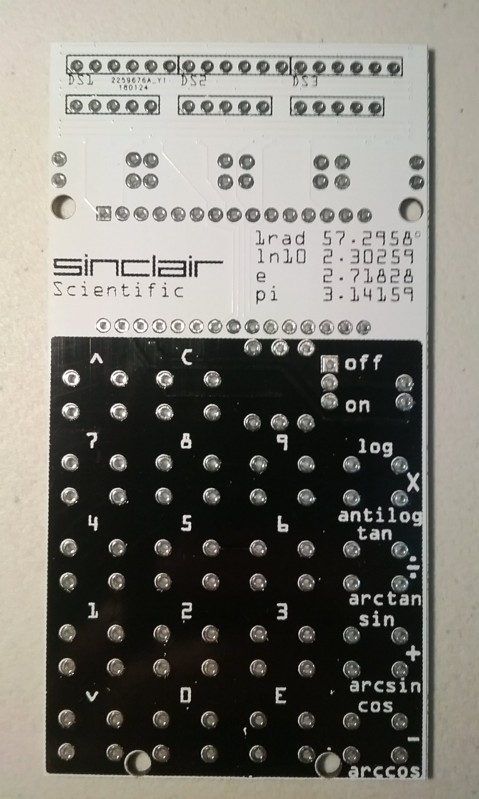
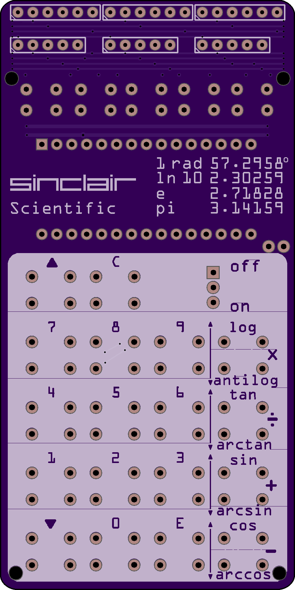
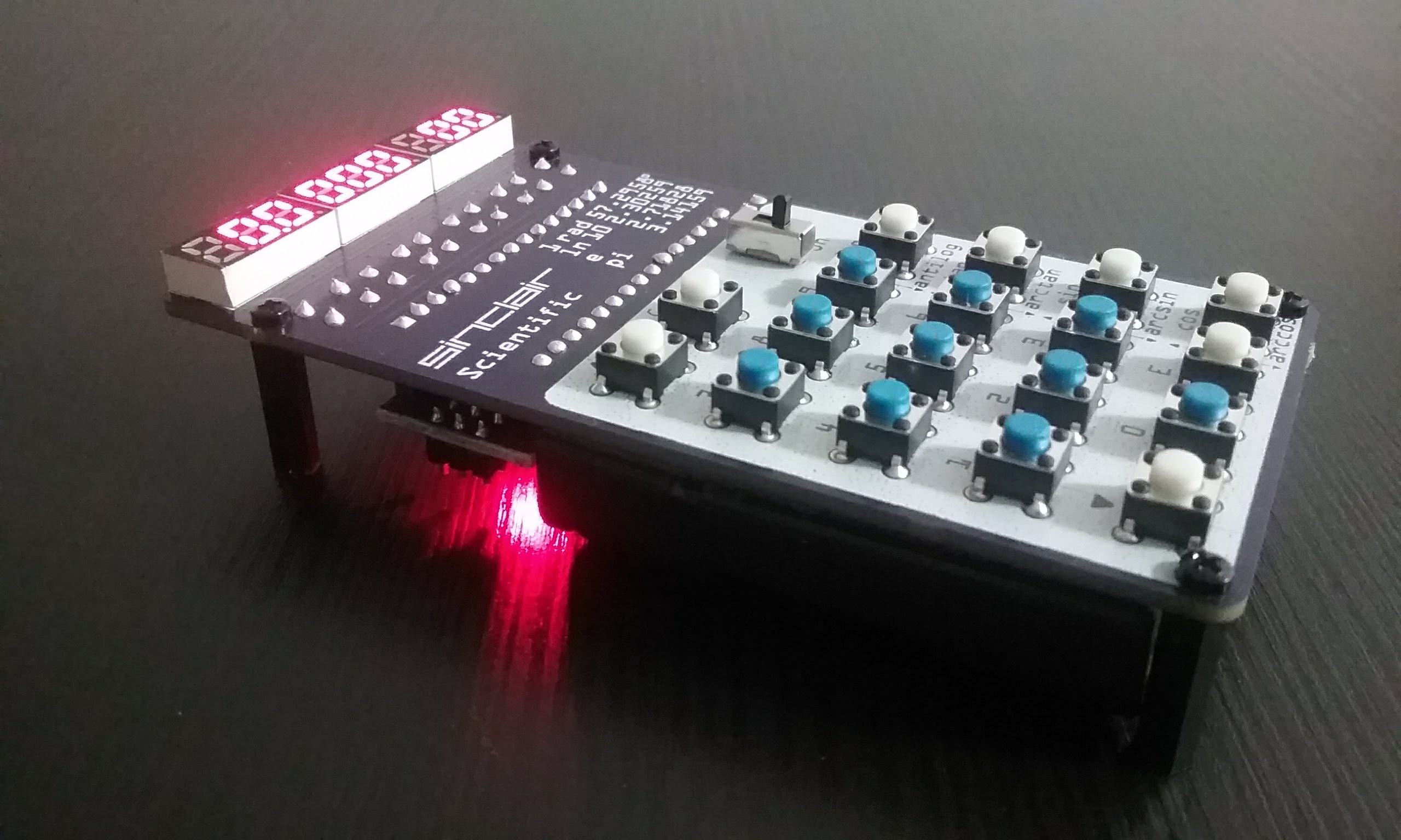
One is quickly assembled. It starts to resemble the original calculator.

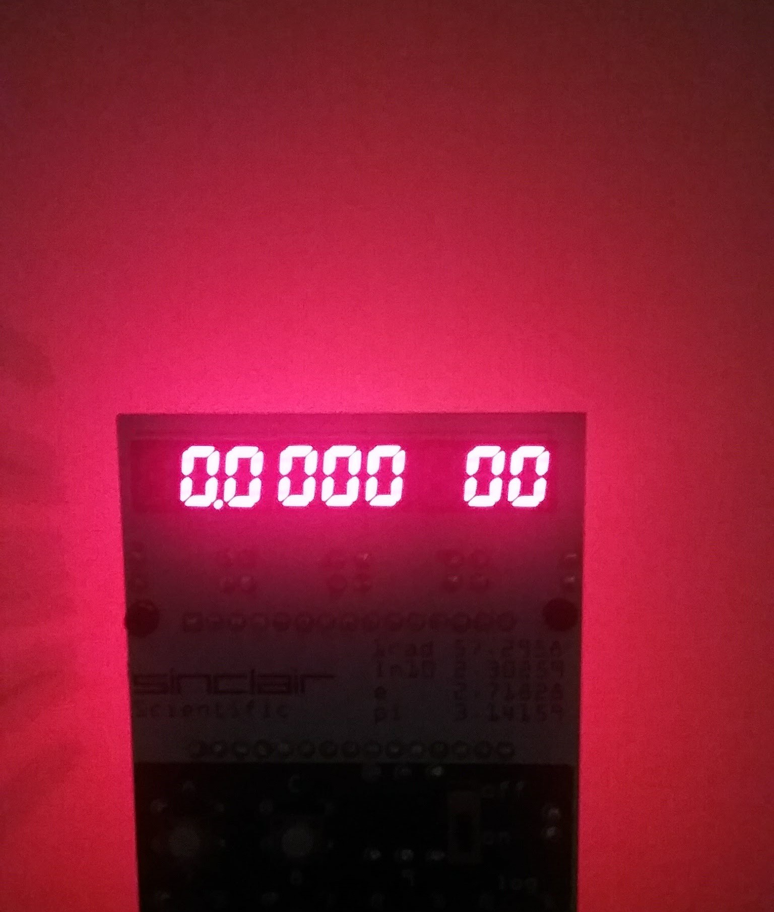
A side effect of the pin assignment is that all 4 LEDs in the back of the Arduino Nano are lit up (D0,D1,D13,Power). This makes a fantastic backlight or ground effect. But I digress,
The main problem with this board is that at its heart, it is still a KIM-1 circuit. Press two keys together and the same segment in all of the digits is affected.
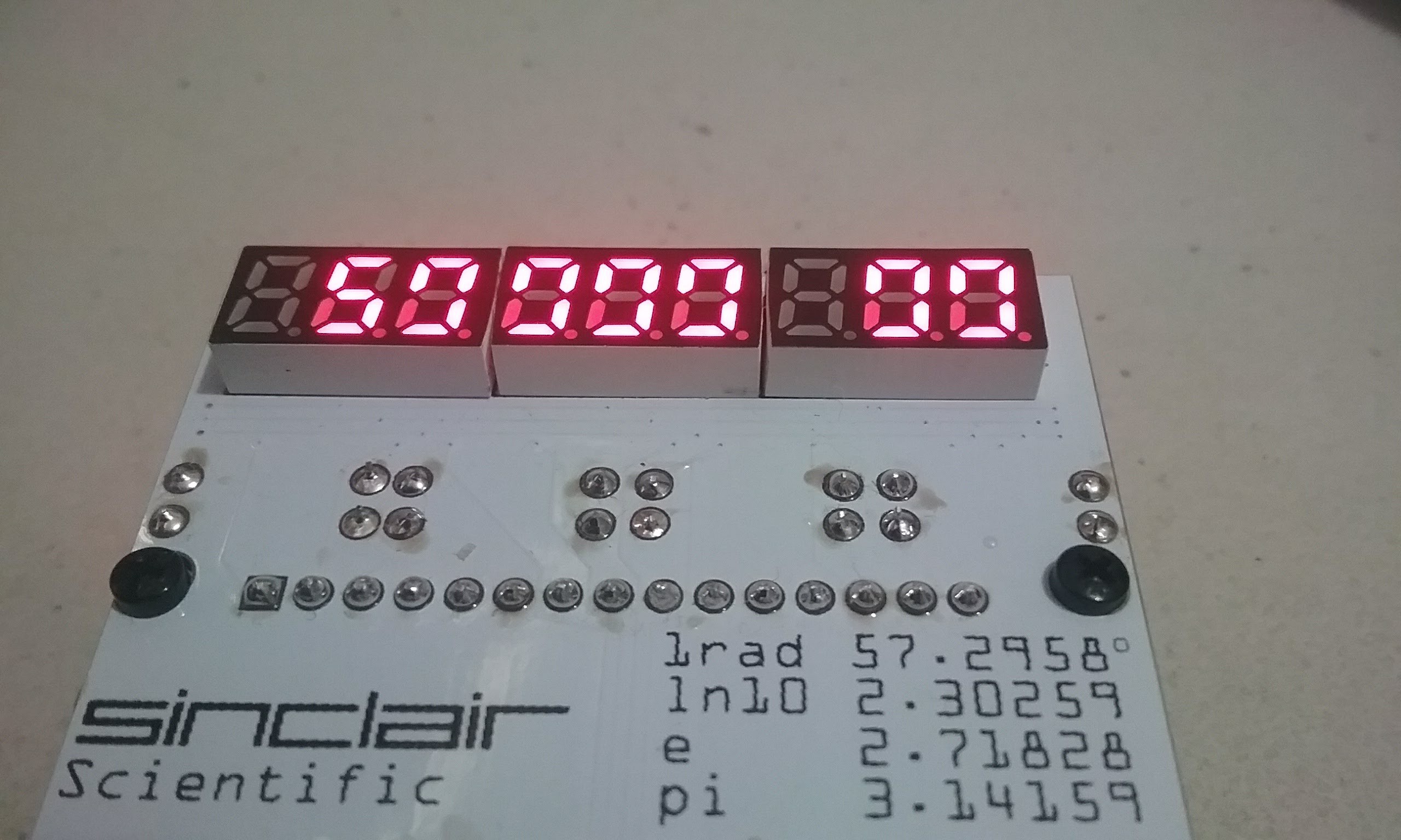
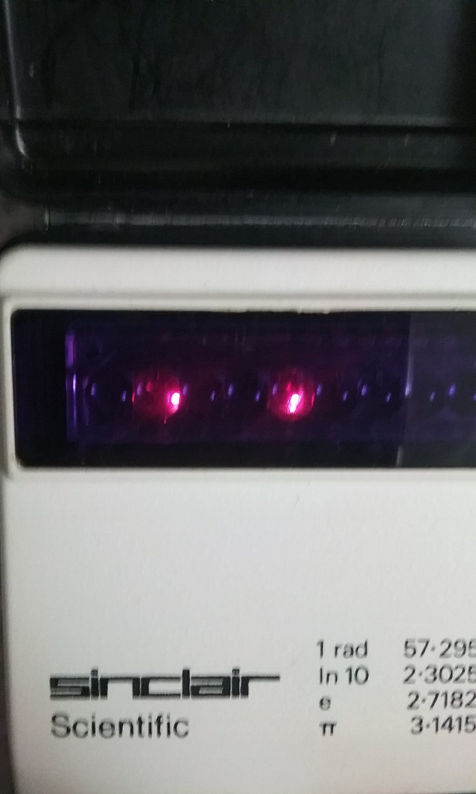
Pressing two keys in the original calculator, instead corrupts the value displayed in two number positions, but the segments do not go dim like on the KIM.
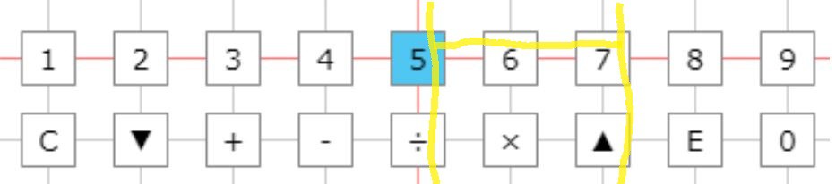
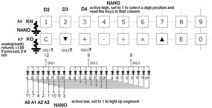
On the online simulator, the red line moves to each digit and if the key is pressed, the top horizontal line (KN) lights up, if a function key is pressed, the bottom horizontal line (KO) lights up. If pressing two keys affects two digits, it means that the column selection lines are connected to the common anode of the displays.
In the example below, if 5 and 7 are pressed simultaneously, if the 5 column is being scanned, the display connected to the 5th and 7th columns will be activated. Once the active selection line reaches the 7th column, the 5th column will be activated as well.
We go back to http://righto.com/sinclair and ponder things for a while. Its funny how one can see things a few times and not realize what is going on. This calculator has a screen with 9 digits, counting the two positions where a minus sign is displayed. The keys are arranged in 9 columns. There is a counter in the CPU.ino file that rotates an active bit in an array. This means that the dActive / d is used as a strobe to select the digit to light up and activate a keyboard column to read.
void updateD()
{
  for (signed char i = 10; i >= 0; i--)
  {
    SinclairData.d[i] = 1;
  }

  SinclairData.dActive += 1;
  if (SinclairData.dActive > 10)
  {
    SinclairData.dActive = 1;
  }
  SinclairData.d[SinclairData.dActive - 1] = 0;
}
While typing this, I realized that the Active value in SinclairData.d[ ] array is a 0 That means that the display in the Sinclair Scientific is a Common Cathode model. Our display is Common Anode. This only affects the polarity of the signals to make a segment light up and the value read at KN and KO, but that is a topic for another day.
The key realization here is that the vertical lines are connected to the common anode pins of the displays. That way, every time the CPU step function is called, a column is selected. The value that's on the pins connected to the LED segments lights up on the selected position. If a key is pressed, it can be read on the KN or KO pins.

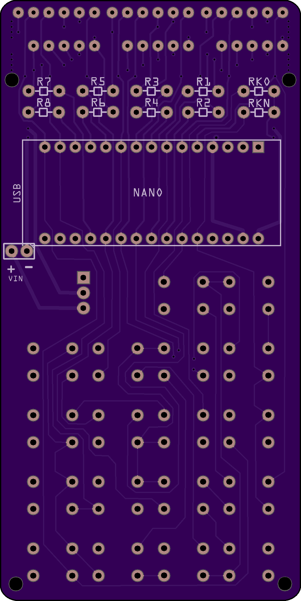
The main difference with this circuit is that the KN and KO pins are always input, instead of the KIM Uno circuit where the LED segment pins are switched from output to input for a moment to read the keyboard. This immediately presents an opportunity to use the input only A6 and A7 pins that went unused in the V1 PCB. Since A6 and A7 are analog input pins, they must be connected either to 5V or ground to get a default value when a key is not pressed. Since the vertical selection lines are active high, and will put 5V on the horizontal lines when a key is pressed, the KN and KO pins must be connected to ground via a resistor. The schematic starts looking like this:
One thing that the schematic does not tell us is the order of the vertical selection lines. In the online emulator, they are arranged in numeric order, but that does not mean it is right.
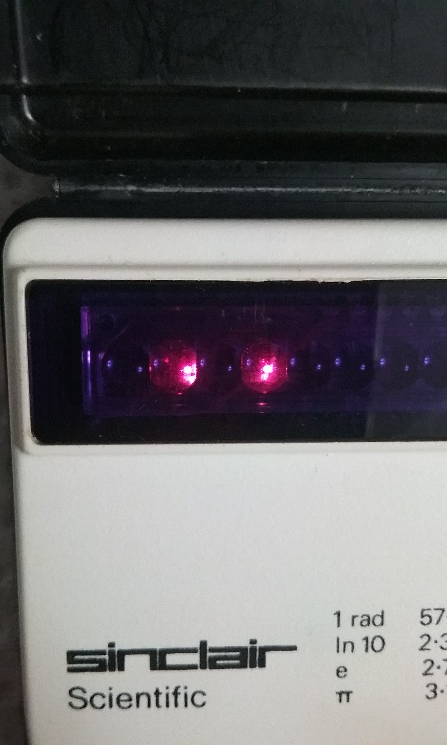
We must come up with a way to determine that order. If two number keys are pressed, two digits on the screen are corrupted. To make things simpler to understand, it would be nice to have a way to isolate only one number. It turns out that if the calculator is computing a trigonometric function, the display only shows the dot.
The calculator is sent on a long trip by pressing 00002 < down key > < - > to calculate the arccos 0.0002. This will show a dot on the screen for a minute and a half. We start pressing two keys at a time until we find that 1 and 5 together shows the dot in two places. Success! Press 1 and 7 and nothing happens.
Press 5 and 6 and the dot is copied one position to the right. Now we know that 5 is connected to the second digit.
5 and 7 together copies the dot two positions to the right.
5 and 8
5 and 3
With careful experimentation, we arrive at the following order:
156789234
Press 5 and any other number while calculating arccos 0.0002 and the dot will be copied to another position in the display. The function keys, except for C, which resets the calculator can be verified in the same manner. Press 5 or / and + and the dot will be shown in the penultimate position on the display.
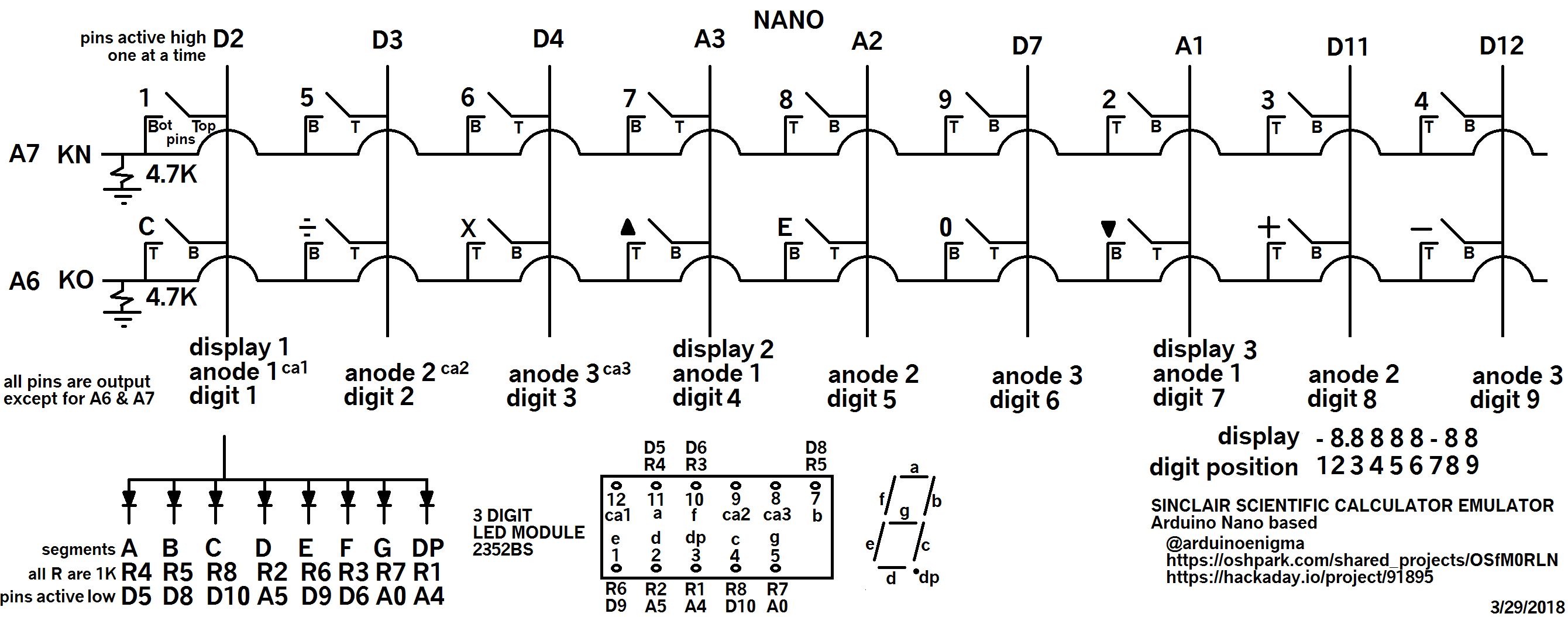
We now have the definitive relationship between keys and digit positions. The schematic below starts to take shape. A bonus of this design is that the serial port pins D0/D1 are free, as well as D13. Serial communication while using the calculator begins to be a possibility now.
In the tradition of Bob (My Spice is a breadboard) Pease, I decided to put this circuit together before committing to designing and fabricating it.
The black and white wires are the column selection lines (common anodes). The red wires are the horizontal lines going back to KN/KO. To simulate a key has been pressed, they connect the white wires to A6 and A7. The green and yellow wires are the LED segment enabling lines, that go through a resistor before going to the cathode of the LED display. The A6 and A7 pins each has an individual resistor connected to ground.
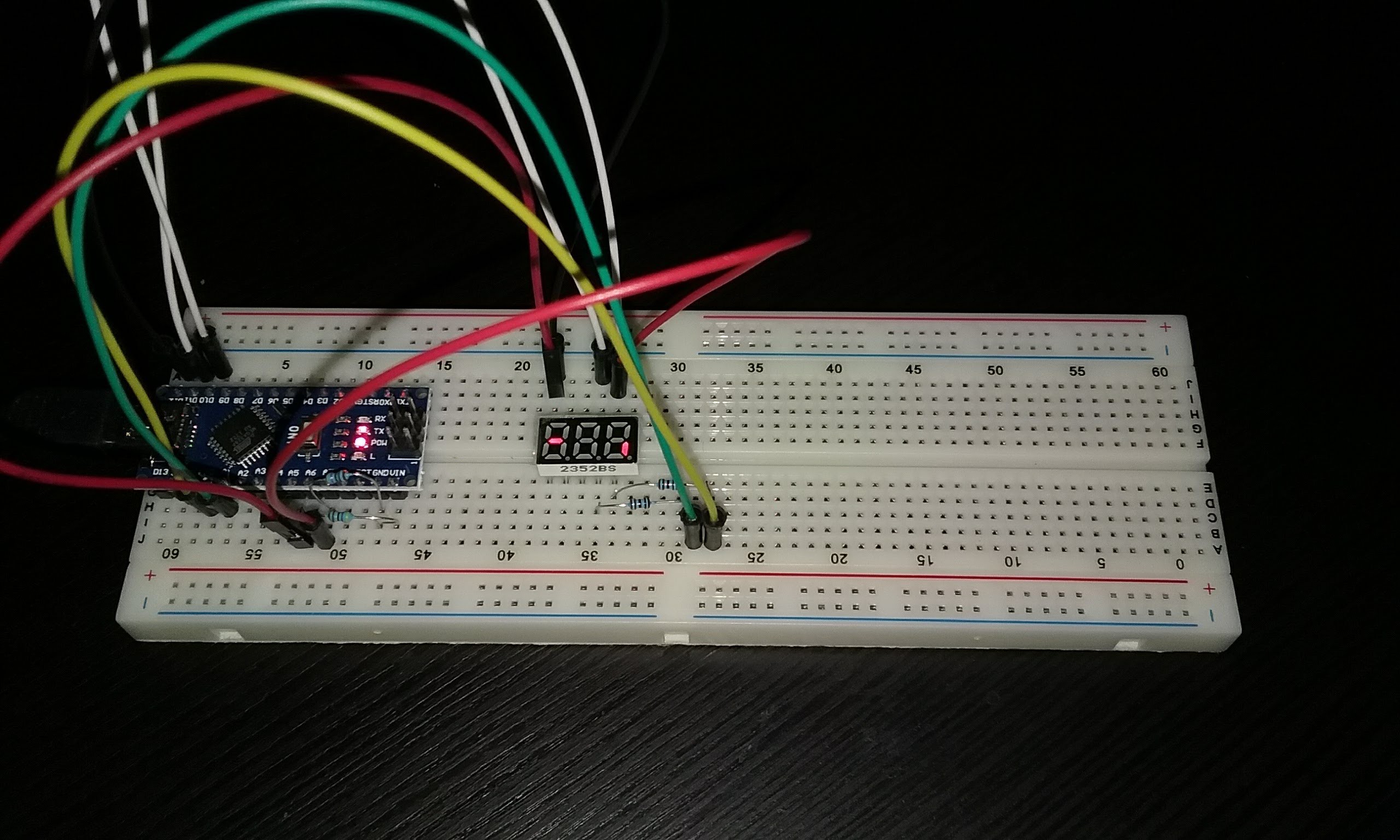
Detail of the resistors. The board is powered by connecting the Arduino to USB

Running a program to read the value of the A6 and A7 pins allows us to verify that no visual corruption occurs when only one key is pressed, connecting the wires at the top of the display to A6 or A7. When the keys are not pressed, the port reads either 0-39. When a single key is pressed, it returns 980-1000. When two conflicting keys are pressed, both are read as 400-500. Thus we can settle on 100 as a threshold value. Any less and the key is not pressed. Anything over that and the key is being pressed.
Here is the code for the experiment shown below:

Now that we have a schematic with the correct selection lines connected to the keyboard and the display, a new board is designed. We will call it V5.
All the tricks learned so far have been used.
1) Tented Vias
2) Negative Silkscreen Mask for the keyboard area.
3) Custom PCB Shape.
In addition, some design features are:
1) The keyboard dimensions are 100% accurate. An emulator can be placed above the original calculator and the keys touch.
2) The displays have been moved up as far as possible and still keeping the 100 mm height. They have been properly spaced now, no need to sand them to make them fit.
3) Minimal use of copper tracks in the front. Definitely no copper in the keyboard or logo area. This was not entirely possible in the keyboard area and a couple of copper traces in the top layer were hidden underneath the 8 key. When assembled, only the horizontal lines at the top are visible.
4) The keyboard resistors needed to bias KO and KN have been moved to the top of the board, away from the keyboard area. This keeps the keypad area very clean, no copper or extra components there.
5) The standoffs are now size M2 and are placed in the corners for stability.
6) The footprint for the resistors has been reduced to .2 inch so 10 1/8 W resistors fit at the top.
Overall, I am really pleased with this board. It contains all of the accumulated wisdom so far.
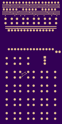
Here is an Oshpark render of the bottom of the board:
And for kicks, here is a view of the bottom copper layer. This was hand routed.

And here is the top copper layer. Besides the horizontal lines at the top, the two tiny traces hidden underneath the 8 key can be seen.
And a gratuitous shot of the basic column diagram being used to double check the PCB wiring.
The back of the PCB as received from Oshpark.
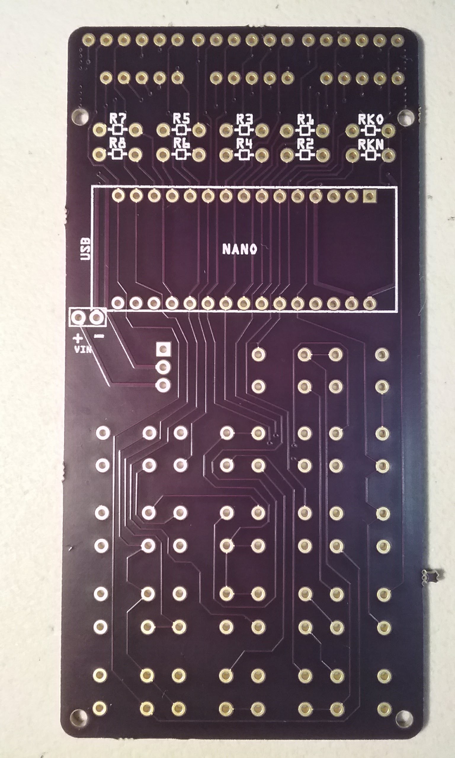
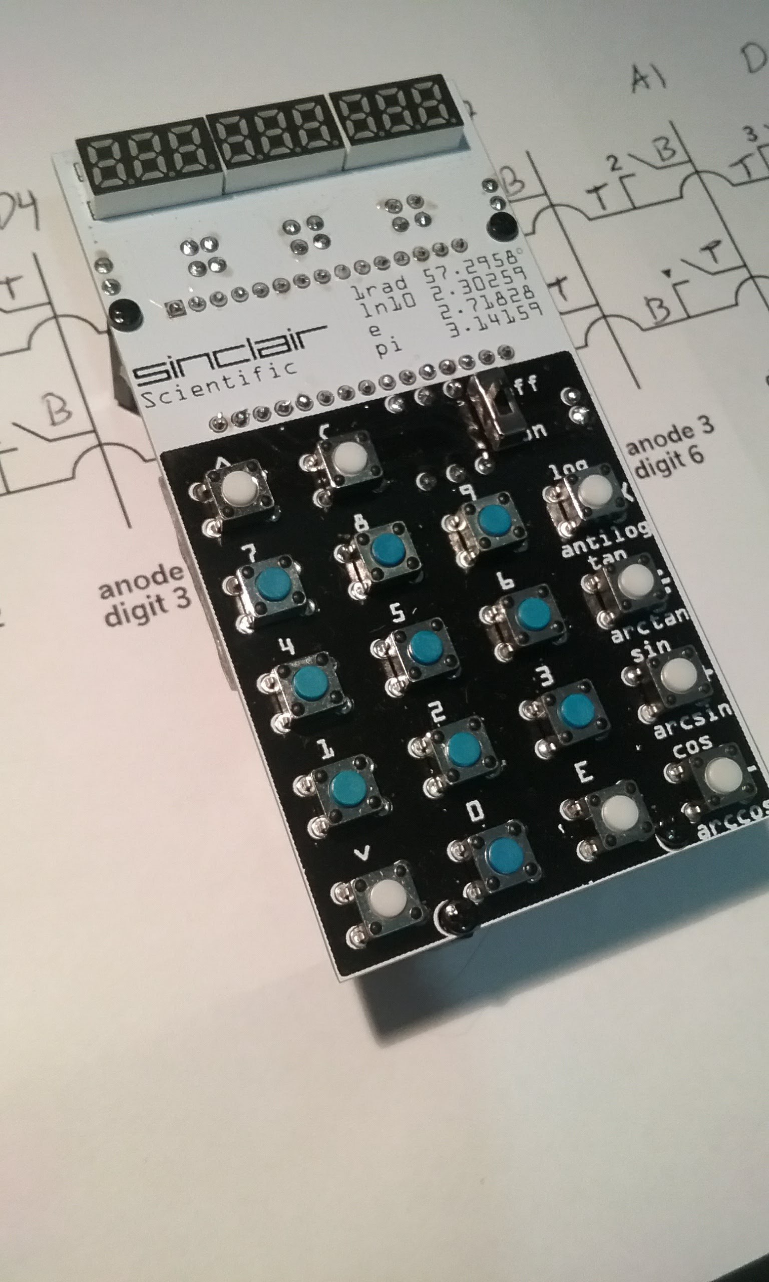
At this point, the assembled PCB is running a slightly modified display code and is showing all digits light up. The code to read the keyboard is not working yet and the battery backpack has not been soldered.
And this is all the copper visible on the top layer.

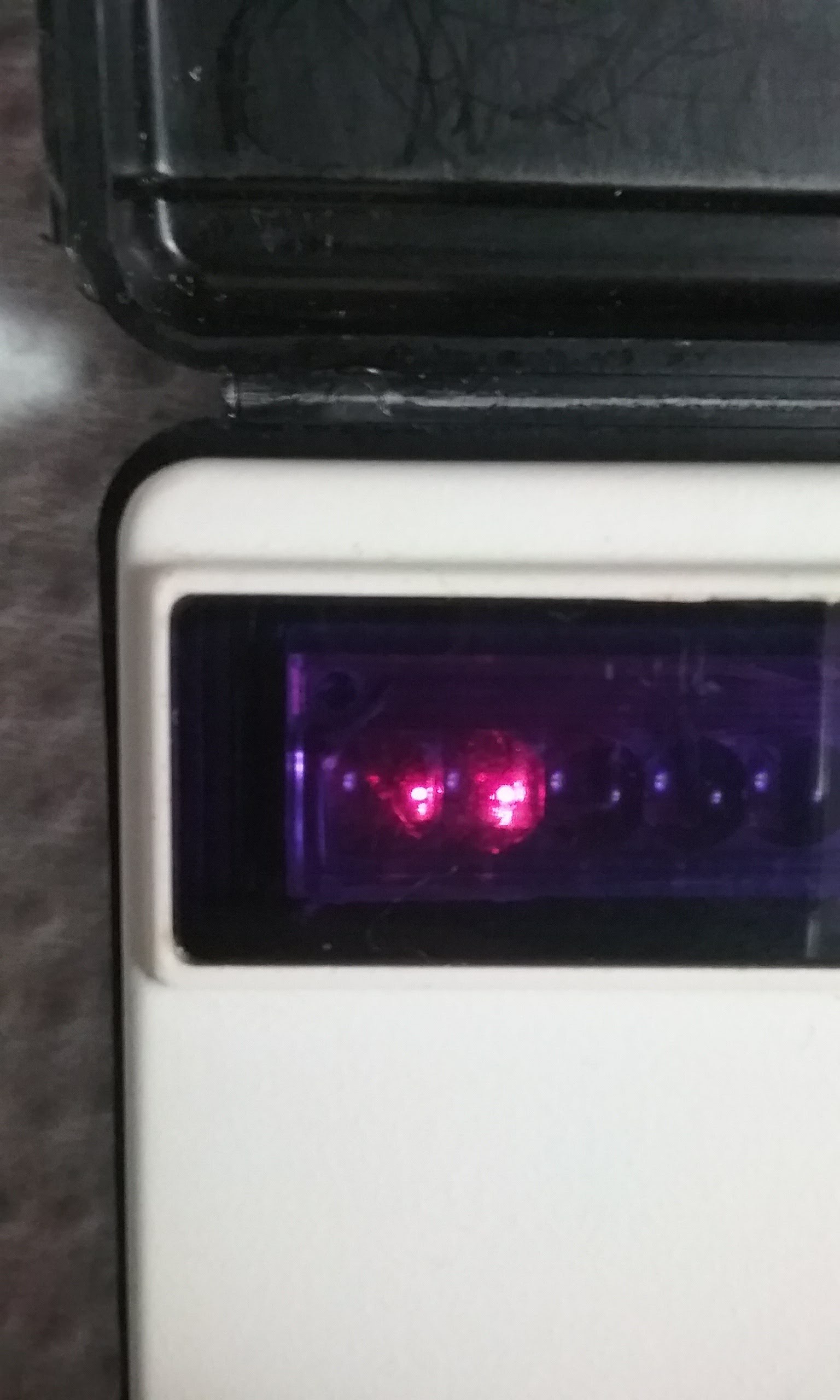
Even if the keyboard code is not working 100% correctly, once the calculator is working on a trigonometric function and only the decimal point is showing, pressing 5 and 6 copies it to the right, this is a hardware behavior. The software has no say in this.
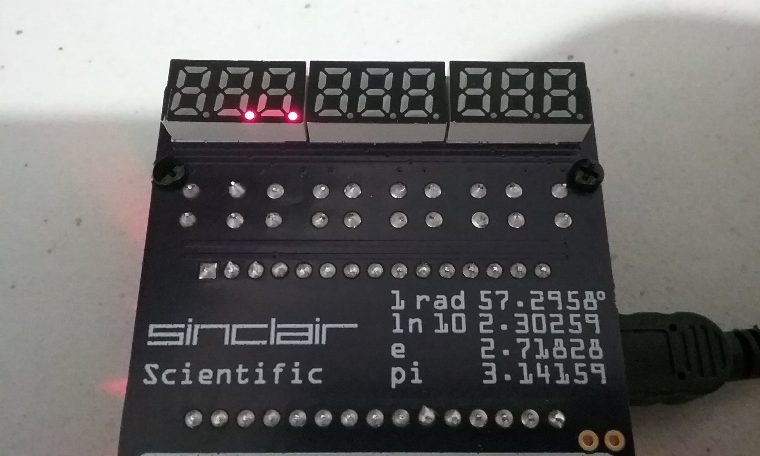
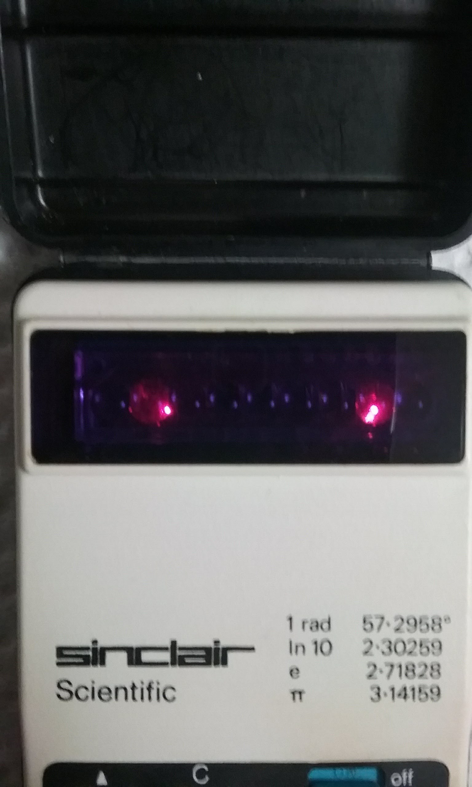
Pressing 5 and 7 simultaneously.
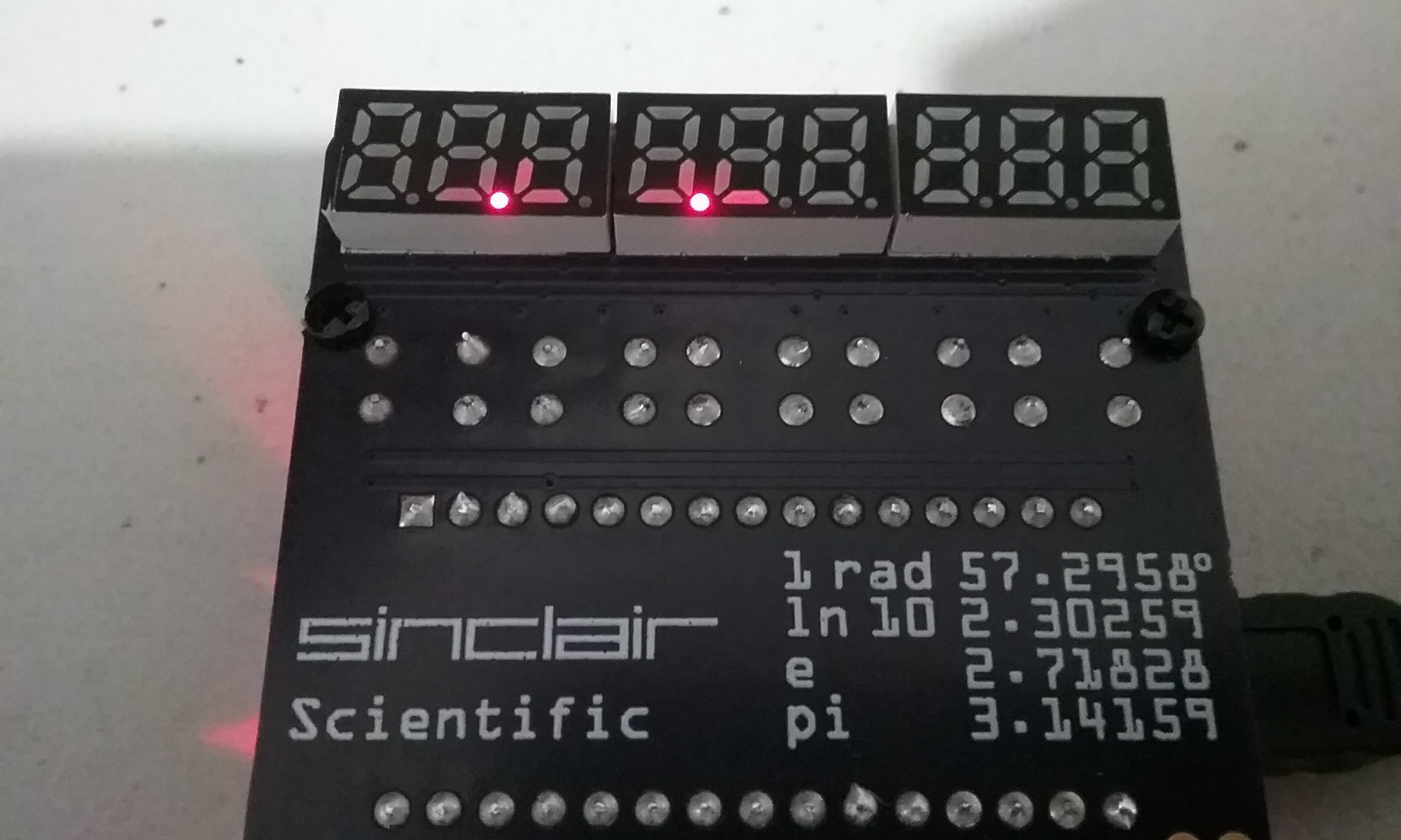
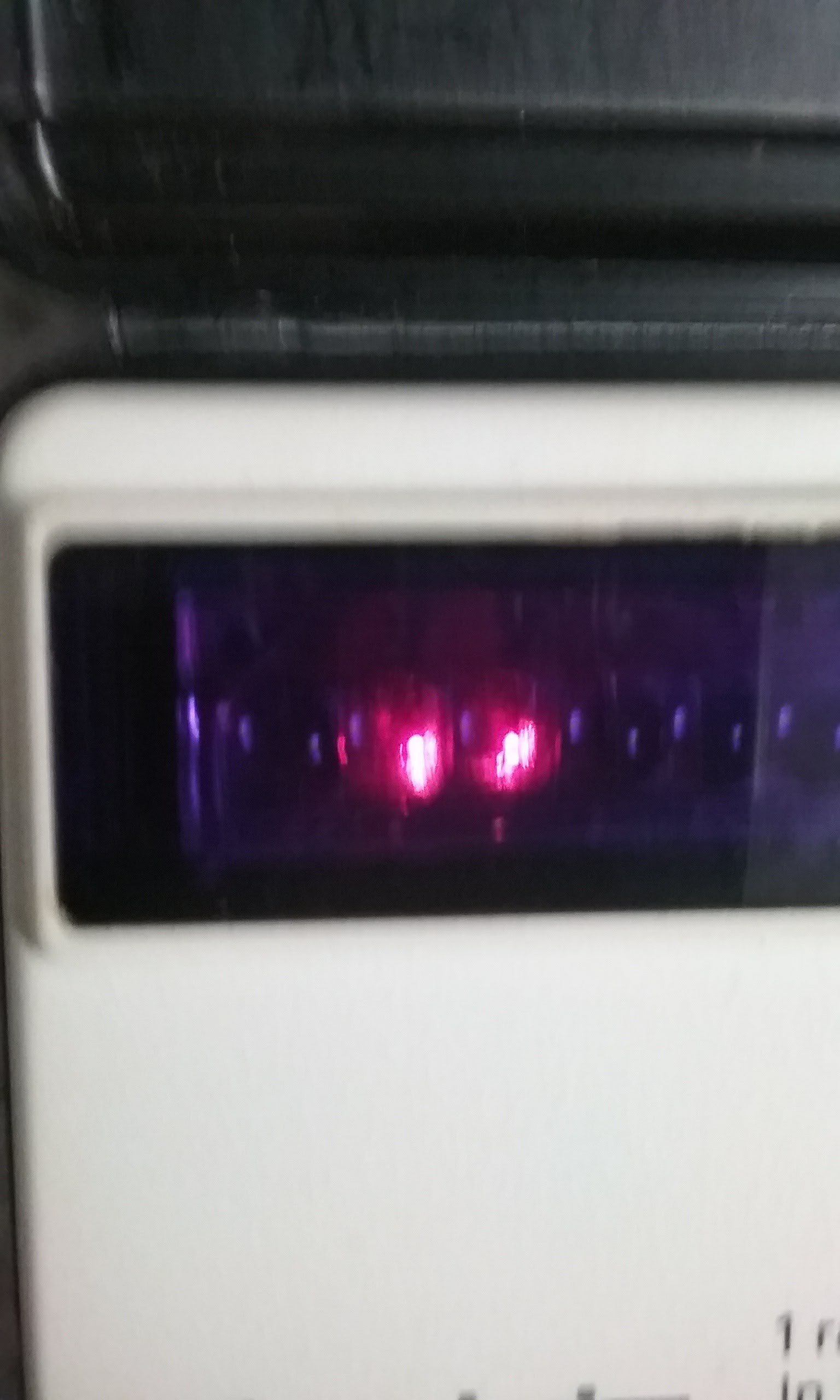
Pressing 5 and 8 together:
Pressing 5 and 4:
Finally, now that we have verified that pressing two keys moves the dot in the same way as the original calculator, let's see what happens when a number is displayed. This behavior is easier to photograph on the emulator than on the bubble displays used in the Sinclair.
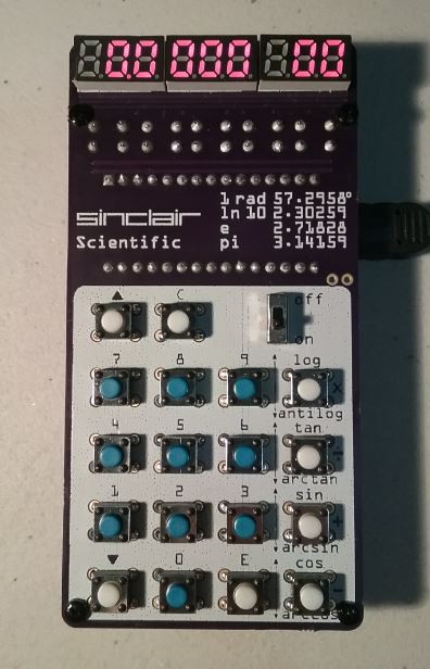
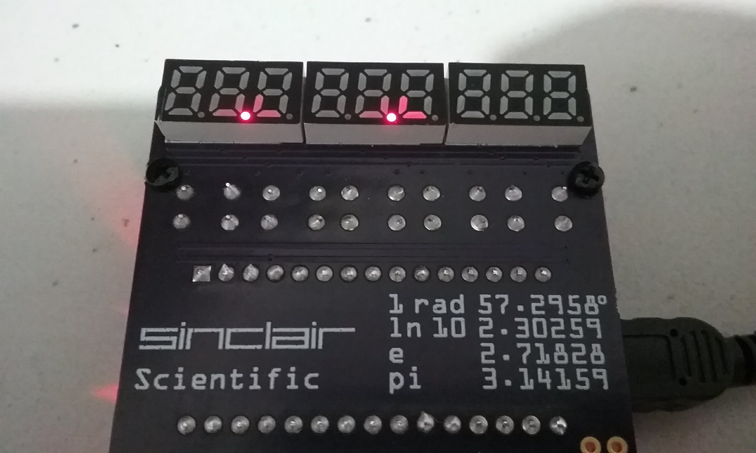
One at a time press and release C 1 5 7 9 5. The display will look like the picture below:
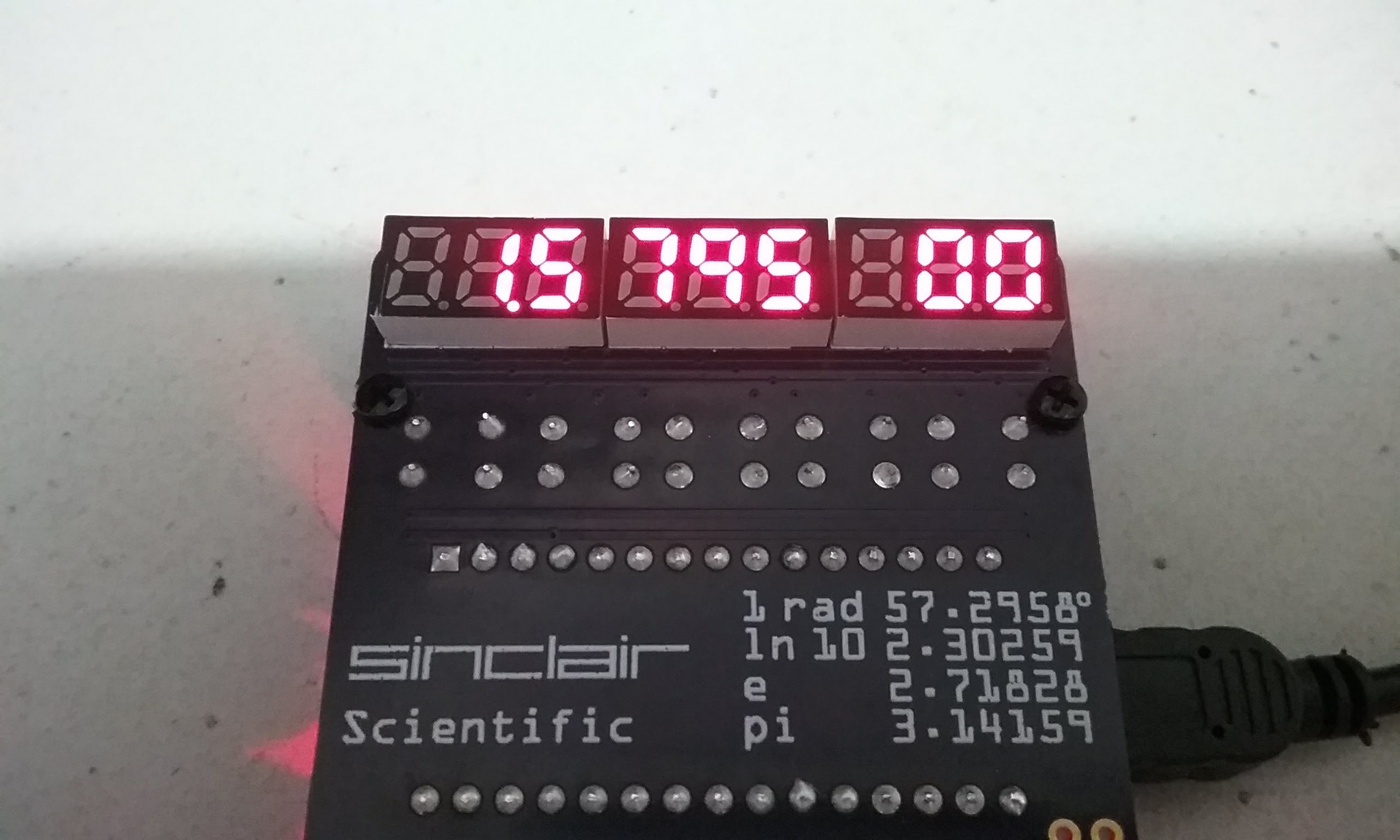
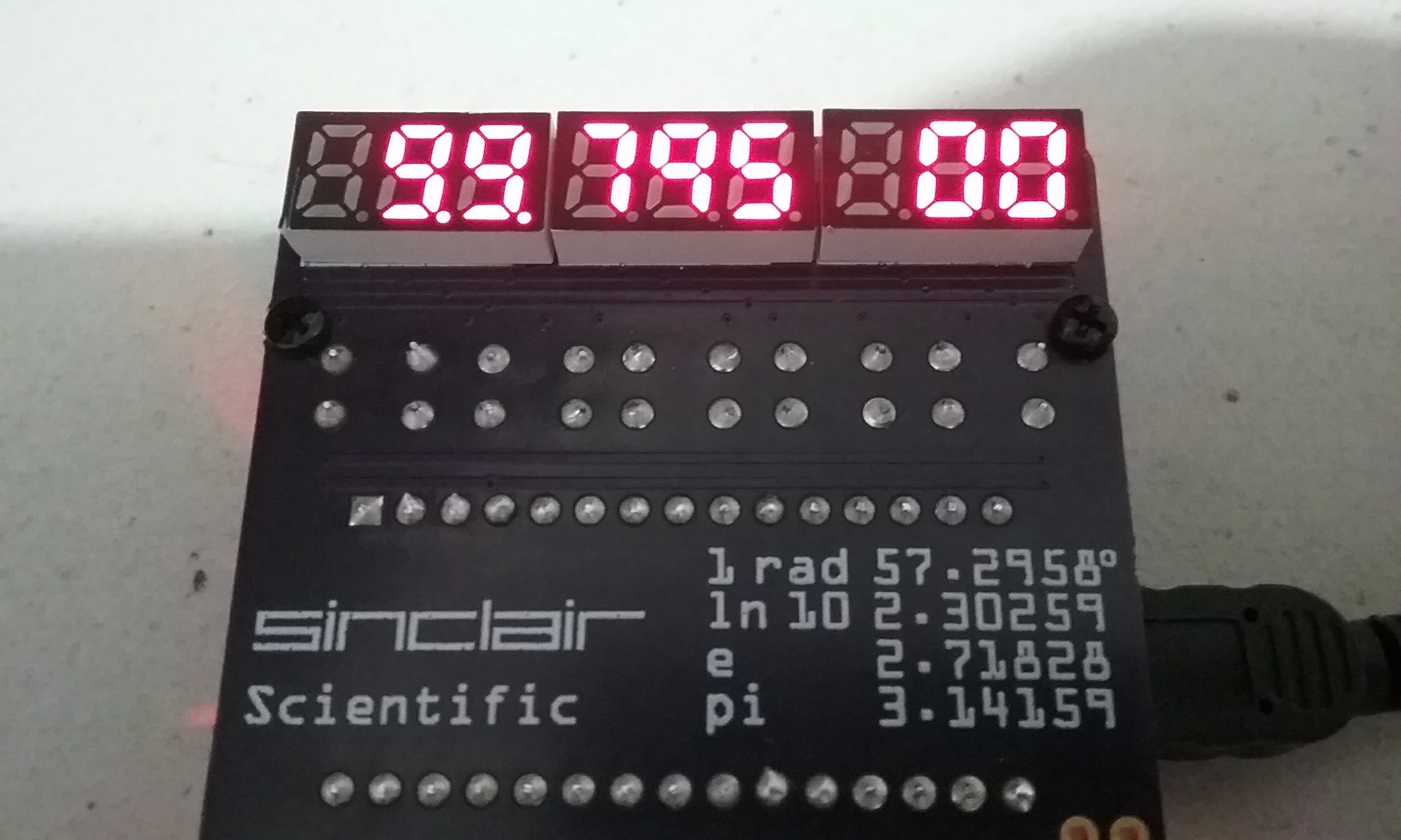
Now that the visible numbers in the display have been entered, press 5 and 6 together. If either 5 or 6 were pressed at this point, the display would not change since all 5 visible digits have been keyed in. But when pressed together, the anodes for the second and third digits are connected by the keyboard, mixing them (ORed). Drawing a 5 on top of a 1 results in a 9 with a tail, compare to the real 9 in position 5. The decimal point is shown on both positions. The original Sinclair display glitches in exactly the same way as the picture shown below:
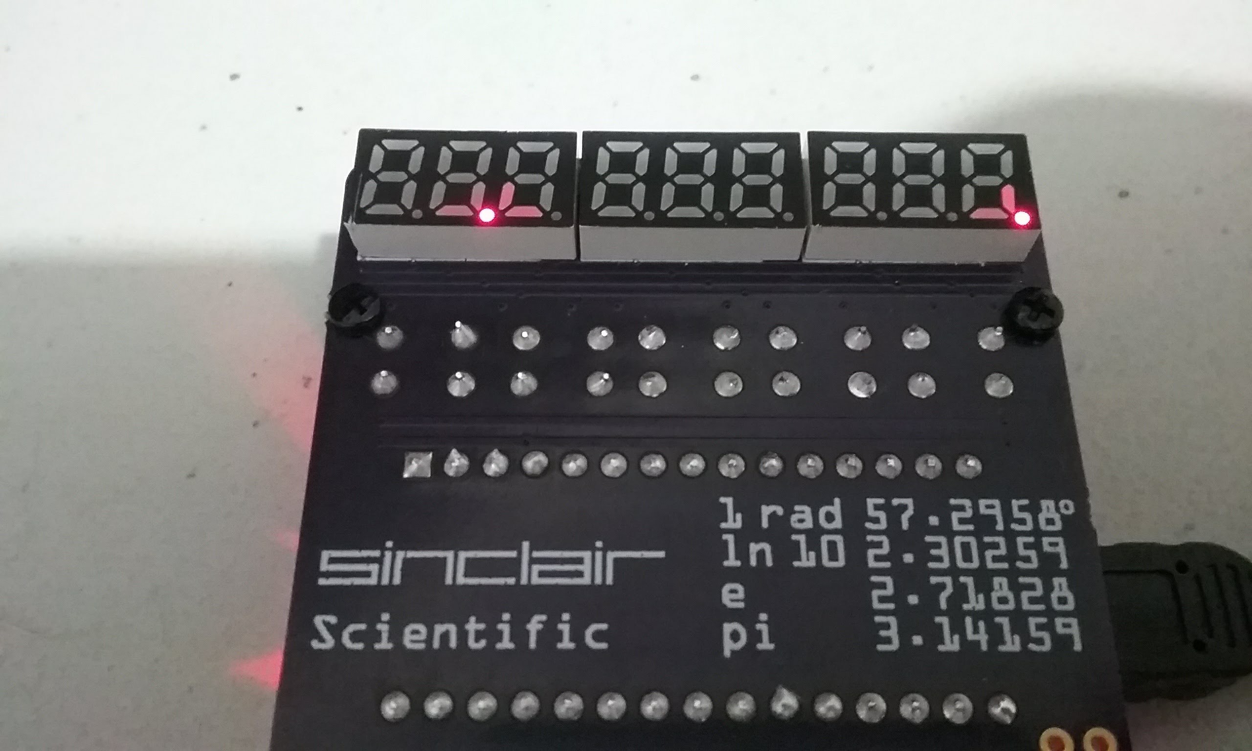
While developing the V5 display software, it became evident that only one column selection pin can be in output mode and outputting a 1. If the other inactive pins are left in output mode outputting a 0, pressing two keys together shorts those Arduino pins and while no damage seems to occur, the two affected digits dim instead of mixing as shown below. The solution is to have the inactive pins switched to input.
Here is a video showing the display glitches:
At this point, the calculator software has been successfully modified to run on the V5 PCB. Two branches have been created on the Github page, one for the V1 and V2 boards, the other one for the V5 board.
Below is the most accurate Sinclair Scientific replica that I know of. It runs accurate software, with the correct speed and visual glitches running on an accurate keyboard and display circuit.
Order the board or download the gerber files here:
https://oshpark.com/shared_projects/OSfM0RLN
Download the software to make it work here:

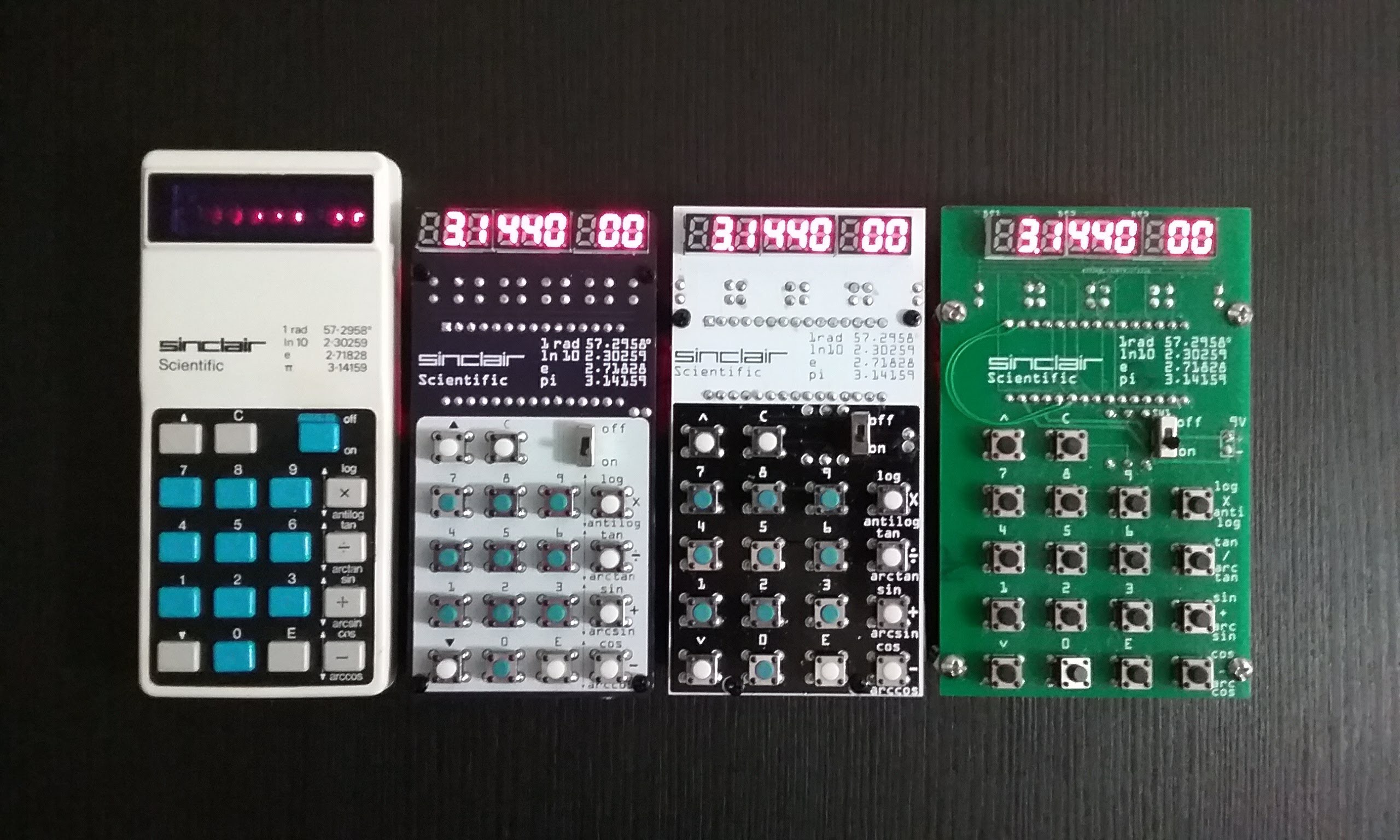
The progression so far:
Sinclair, V5, V2, V1
Discussions
Become a Hackaday.io Member
Create an account to leave a comment. Already have an account? Log In.