 Arduino Enigma
Browsing through ebay, looking for a bubble led display to give the calculator a more authentic look, the following product appears. It is supposed to be a Russian made clone of the HP 5082-7441 9 digit bubble display. With a horizontal dimension of 51mm, it will fit inside the Sinclair Calculator PCB.
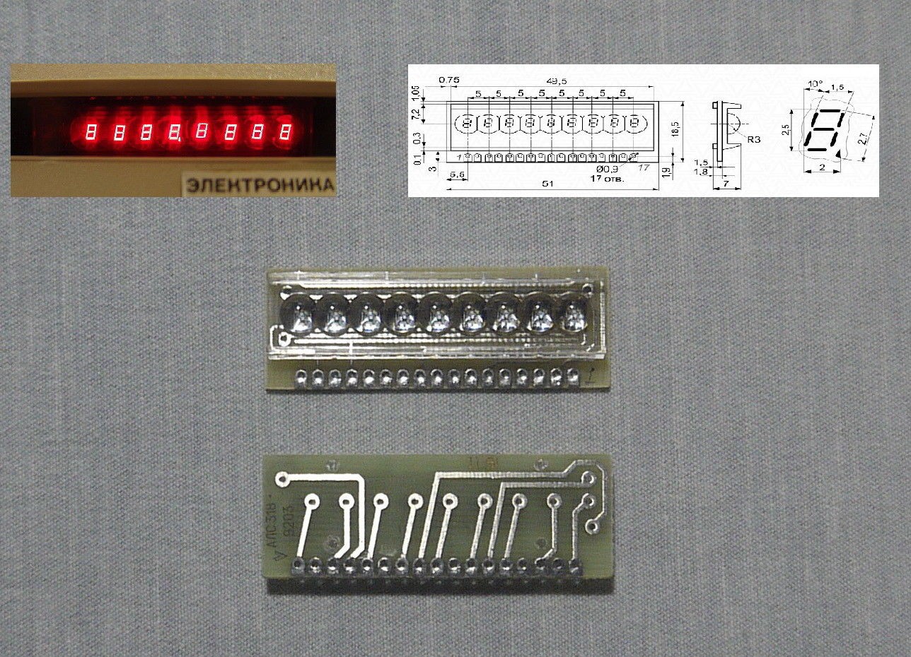
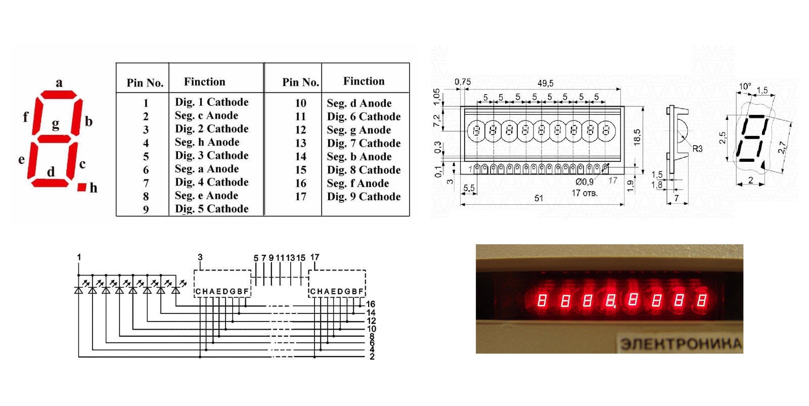
The following datasheet is provided. The display is common cathode. The pin spacing is metric. The connector has 17 pins and it alternates between a digit selection cathode and a segment anode. It does not look too hard to connect to the existing calculator circuit.
To replace the modern LED modules in the calculator with a bubble display, first the LED modules will be deleted, and the current limiting resistors will have to be moved down to accommodate the increased height of the bubble module. The change from a common anode to a common cathode display will be handled exclusively in software. The only wiring change is that RK0 and RKN will be changed from pulldown to pullup resistors.
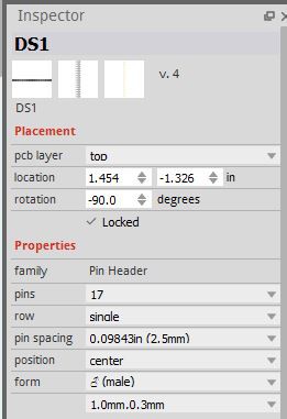
Sometimes, just sometimes, Fritzing comes through by having the exact component one is looking for. In this case, a parametric connector. The amount of pins (17) and the pin spacing (2.5mm) can be specified. Looks like this will be an exact fit.
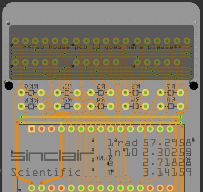
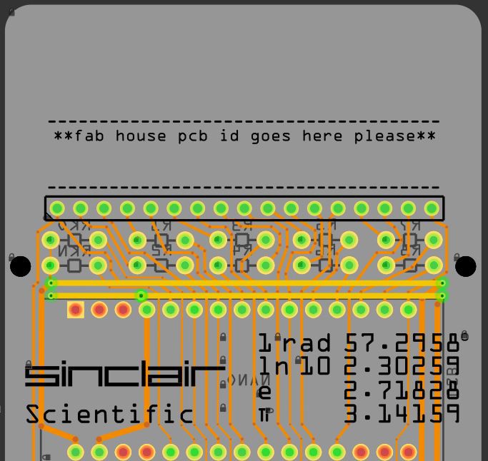
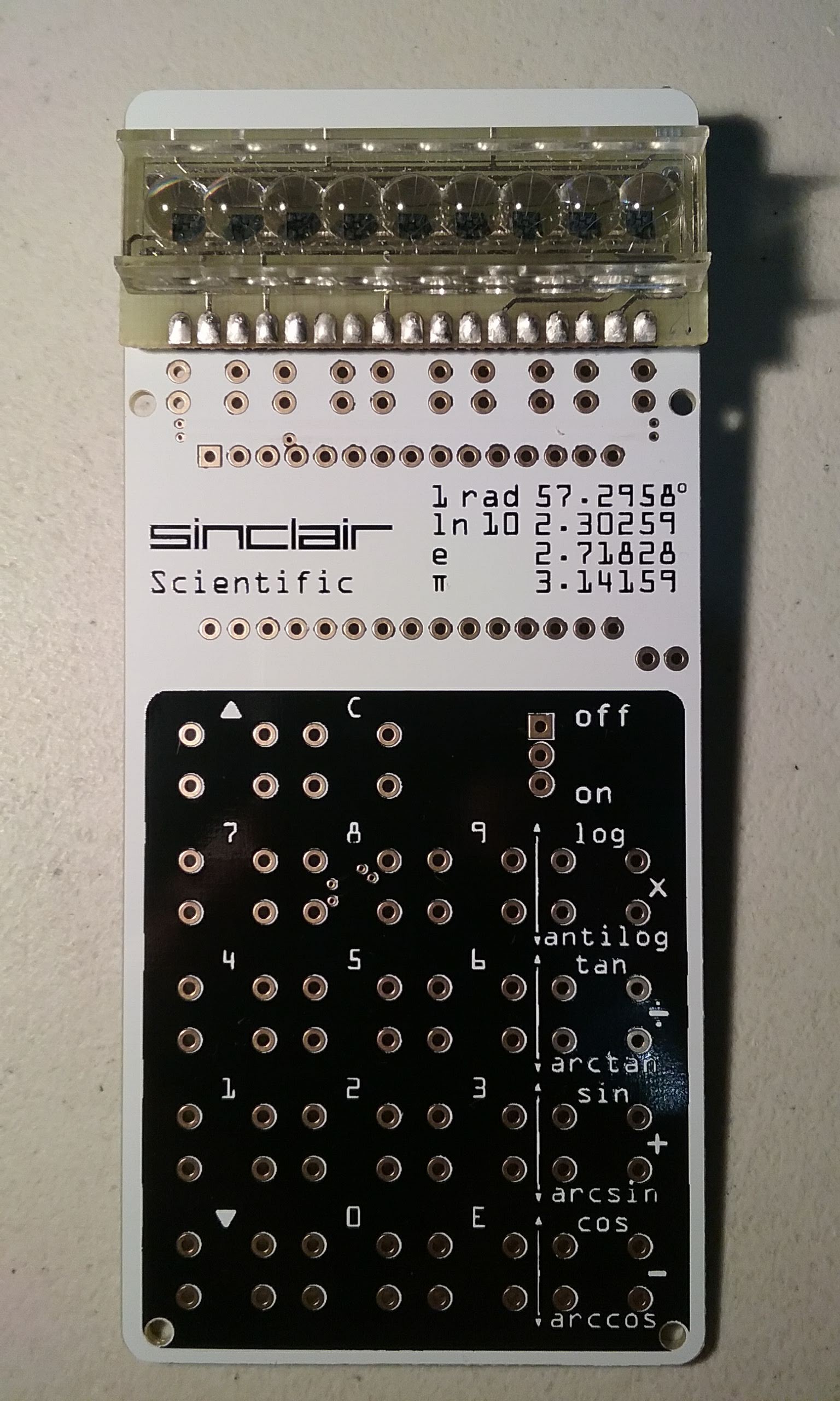
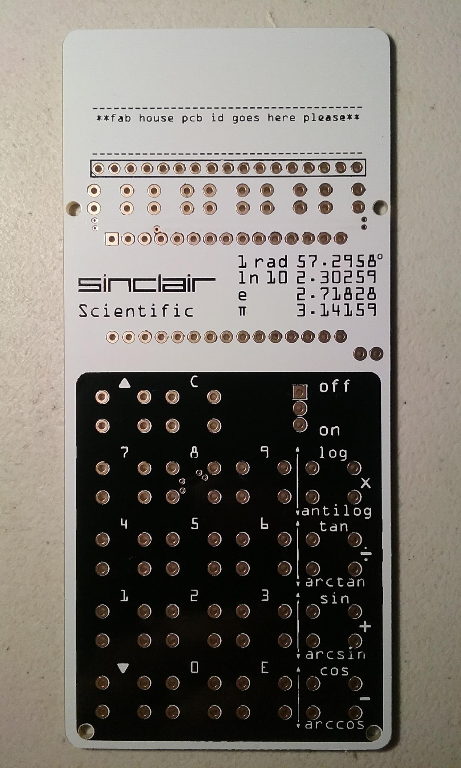
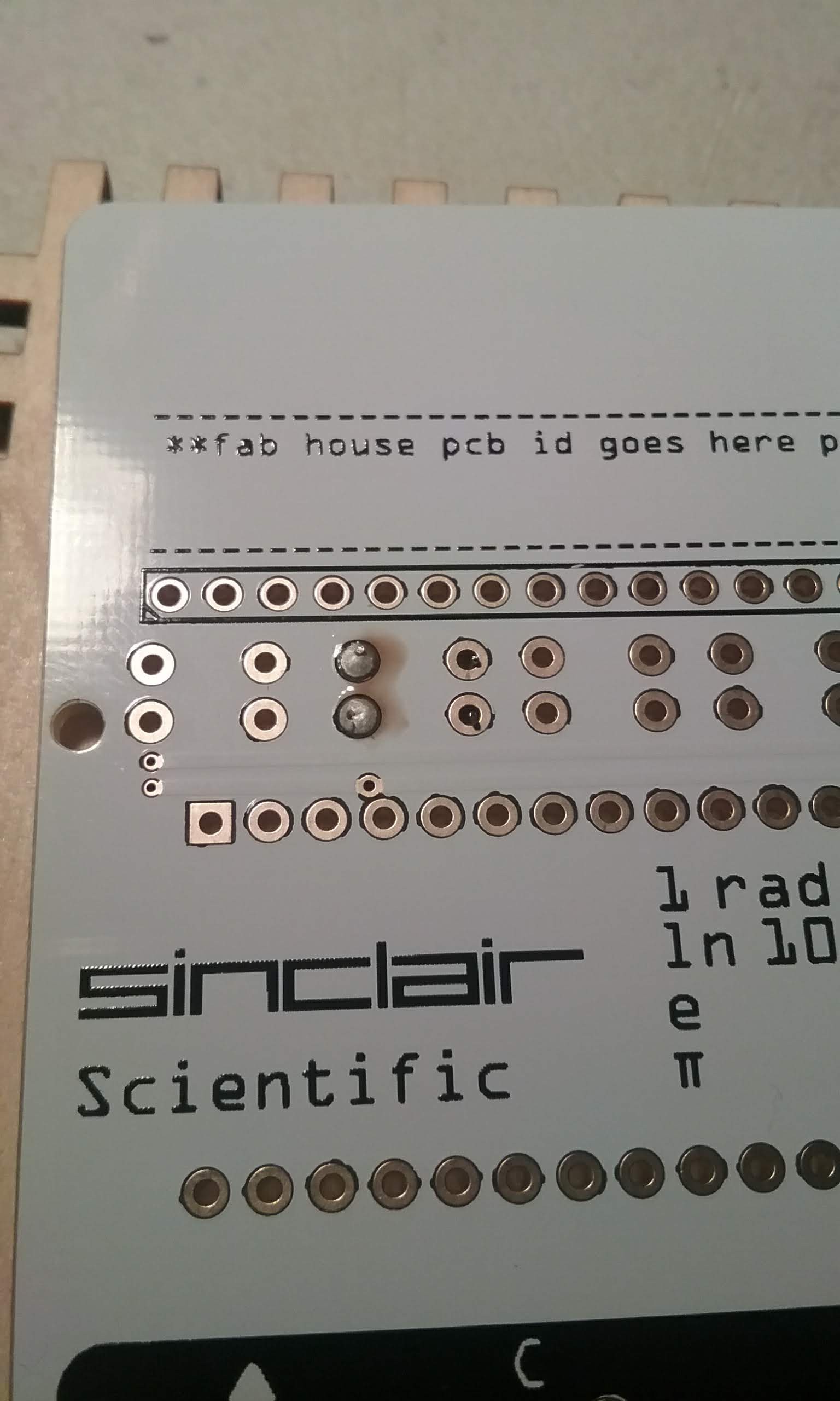
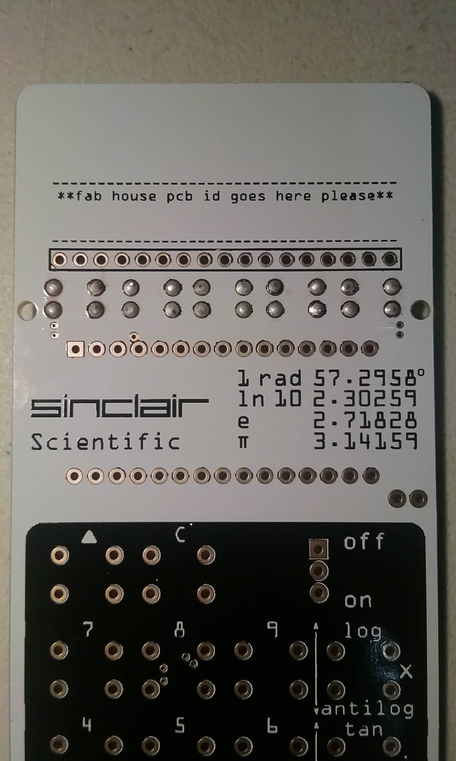
The new PCB is laid out with the new connector and a space is dedicated for the fab house to put their job number. We do not want those extra markings in an inconvenient place, like next to the Sinclair logo. It has happened before. As an interesting note, there is no copper above the 17 pin connector. Note that RKO and RKN are now pull up resistors.
We will be ordering this board from PCBWay.com The ordering process is the usual, describe the size, layers, thickness, board color and decide if the boards will be Lead-free or ENIG finish and submit the Gerbers.
When placing an order, try selecting a few more boards than you want and see what it does to the price quoted. In this case, I was able to get 20 boards instead of 10 for a few bucks more.
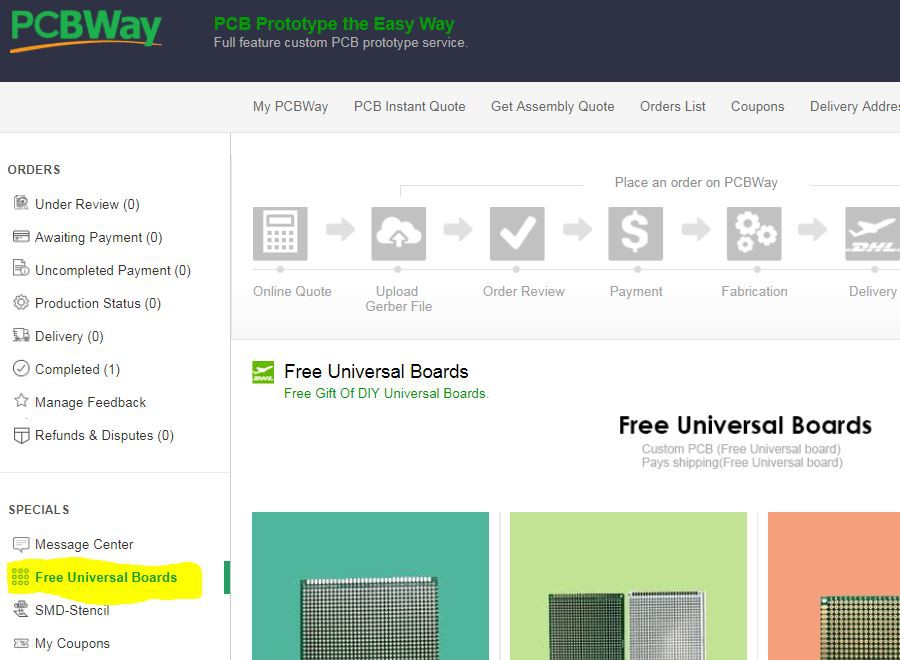
While ordering, you can also take advantage of the Free Universal Boards option and get some free perfboard for some future projects.
While the boards are being fabricated, the progress can be tracked.

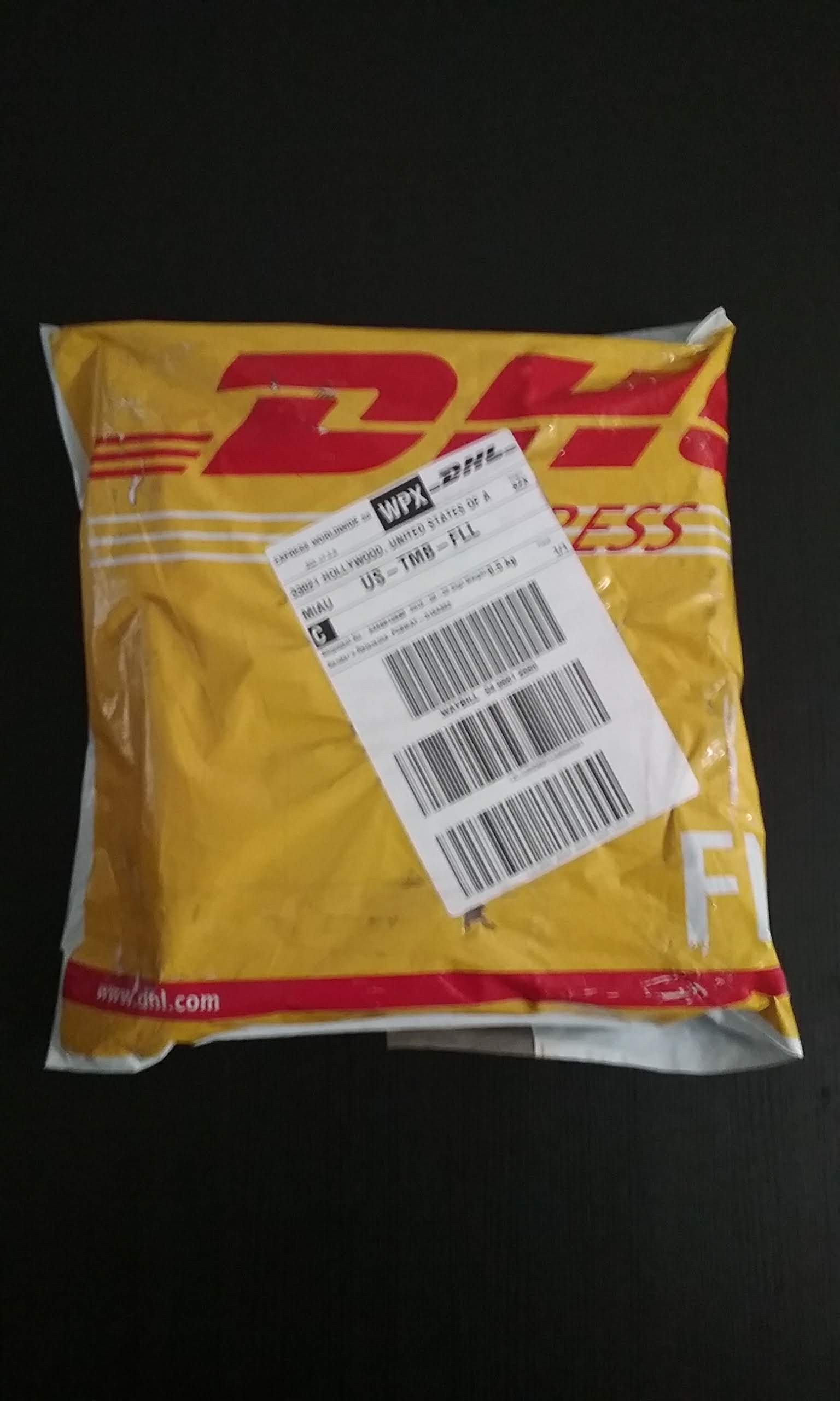
48 hours later, the package is handed to DHL and 3 days later it shows up. One gets spoiled after trying DHL express, order boards and receive them in 5 days including weekends.
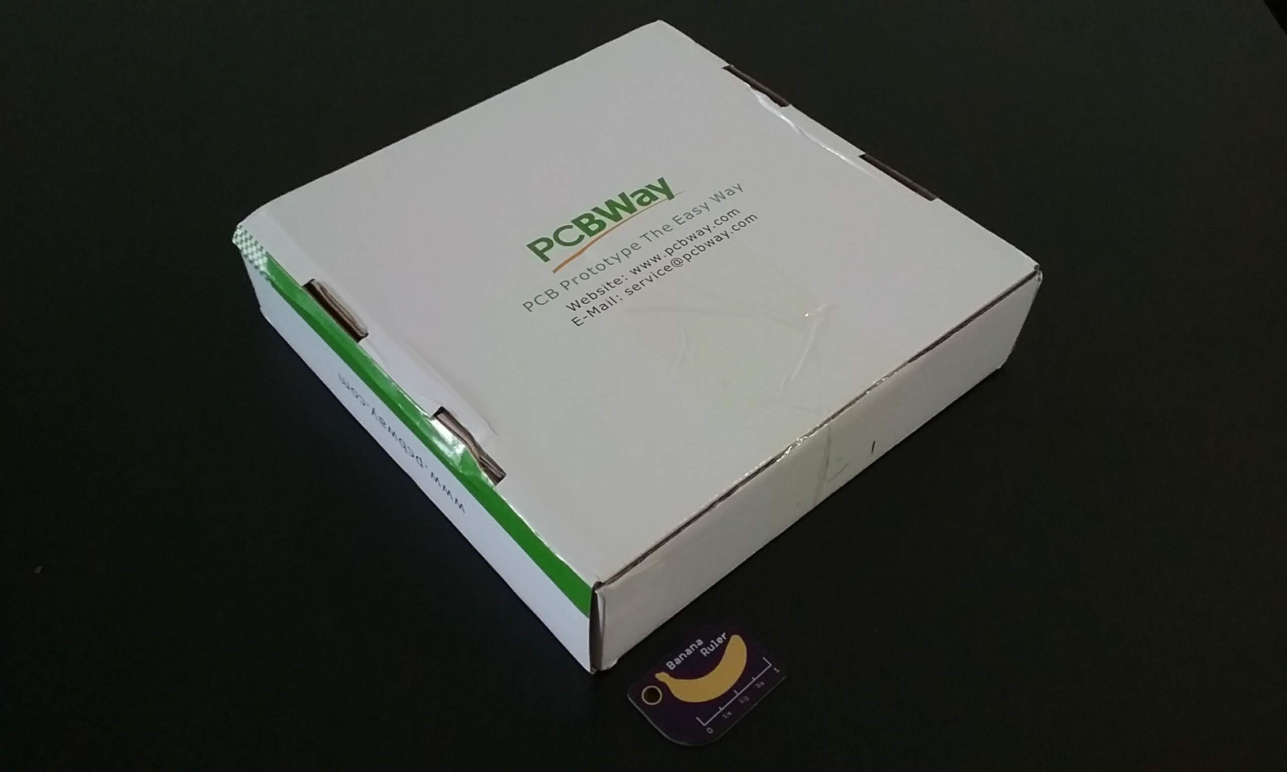
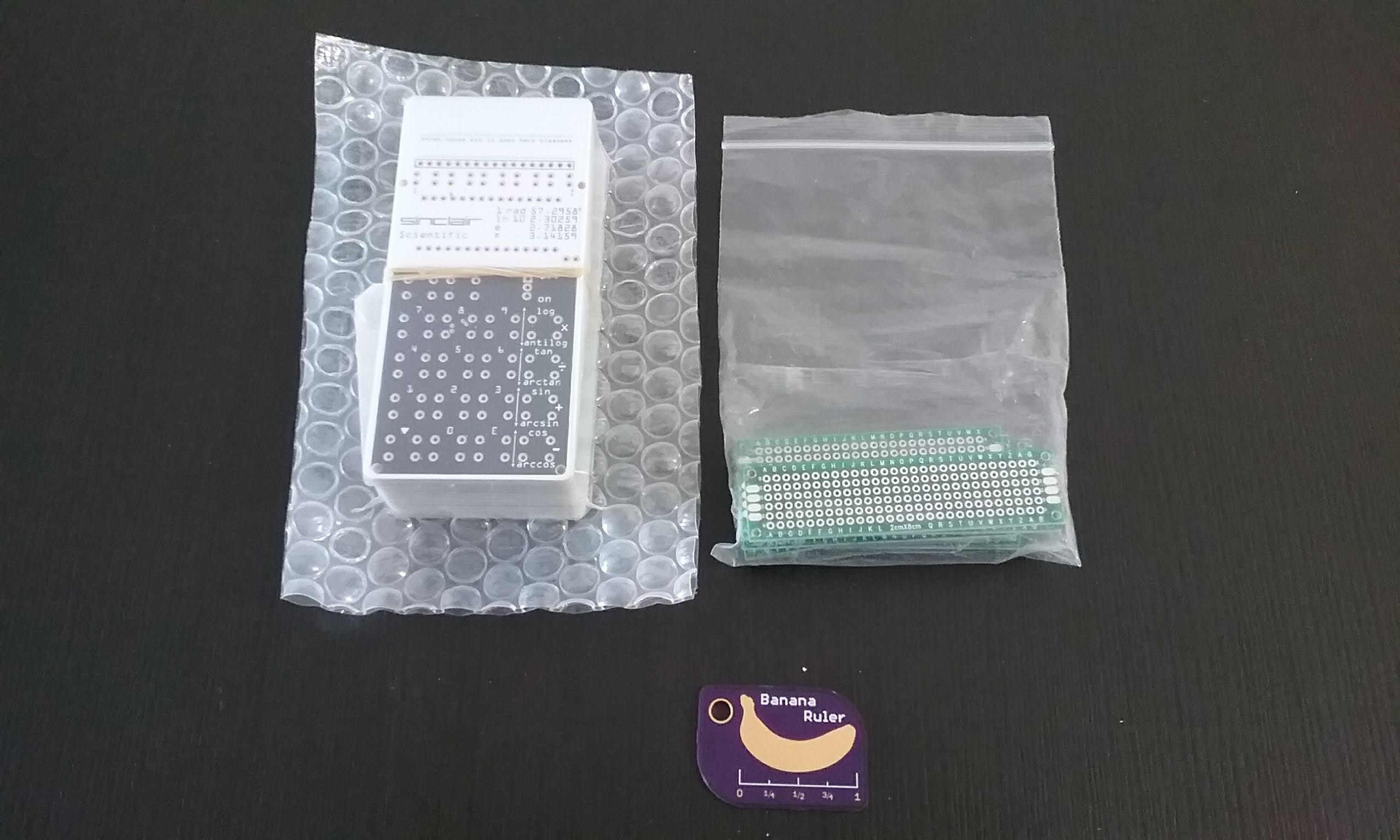
Inside is this good looking box. Banana for Scale.
The boards are packaged in the usual combination shrink/bubble wrap. The free perfboards are nice...
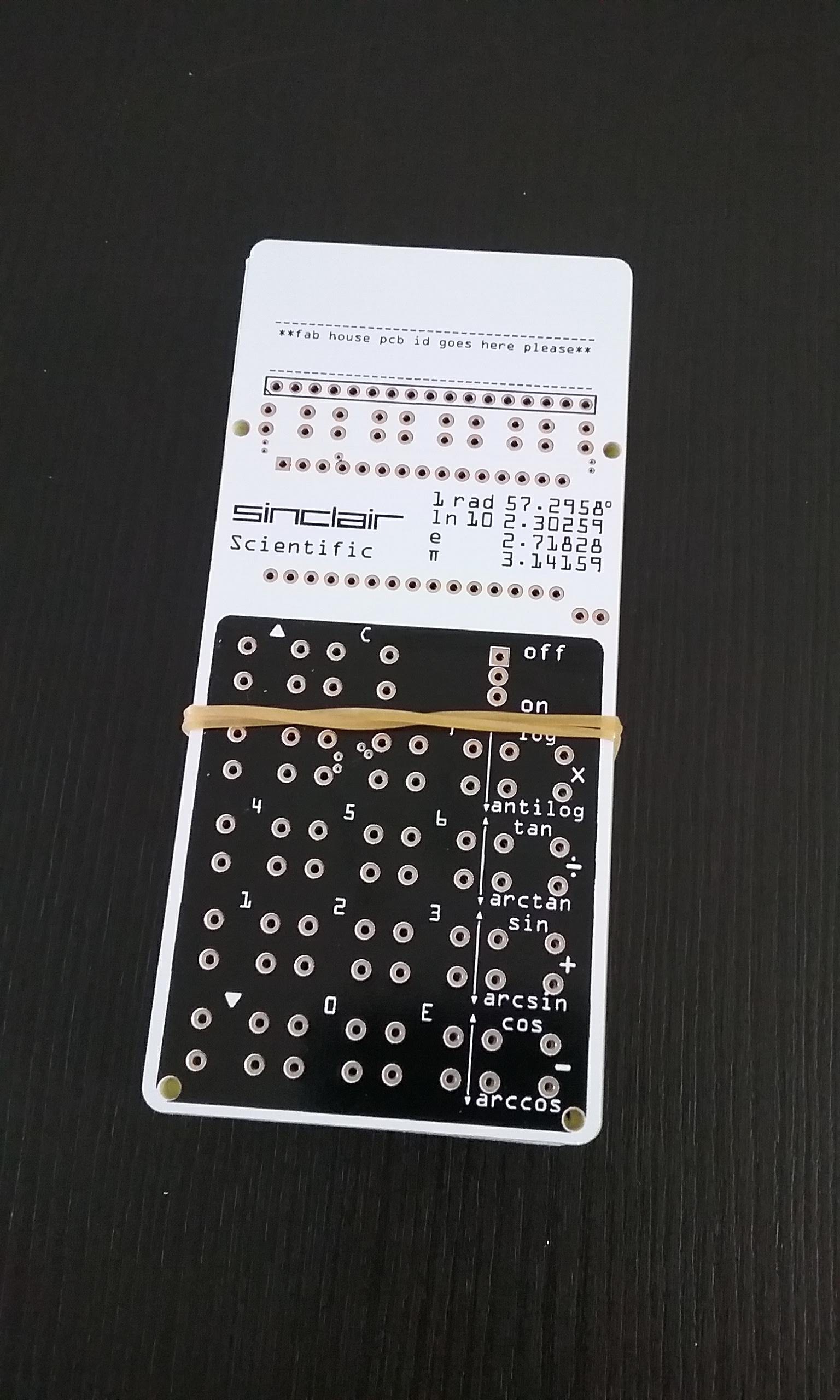
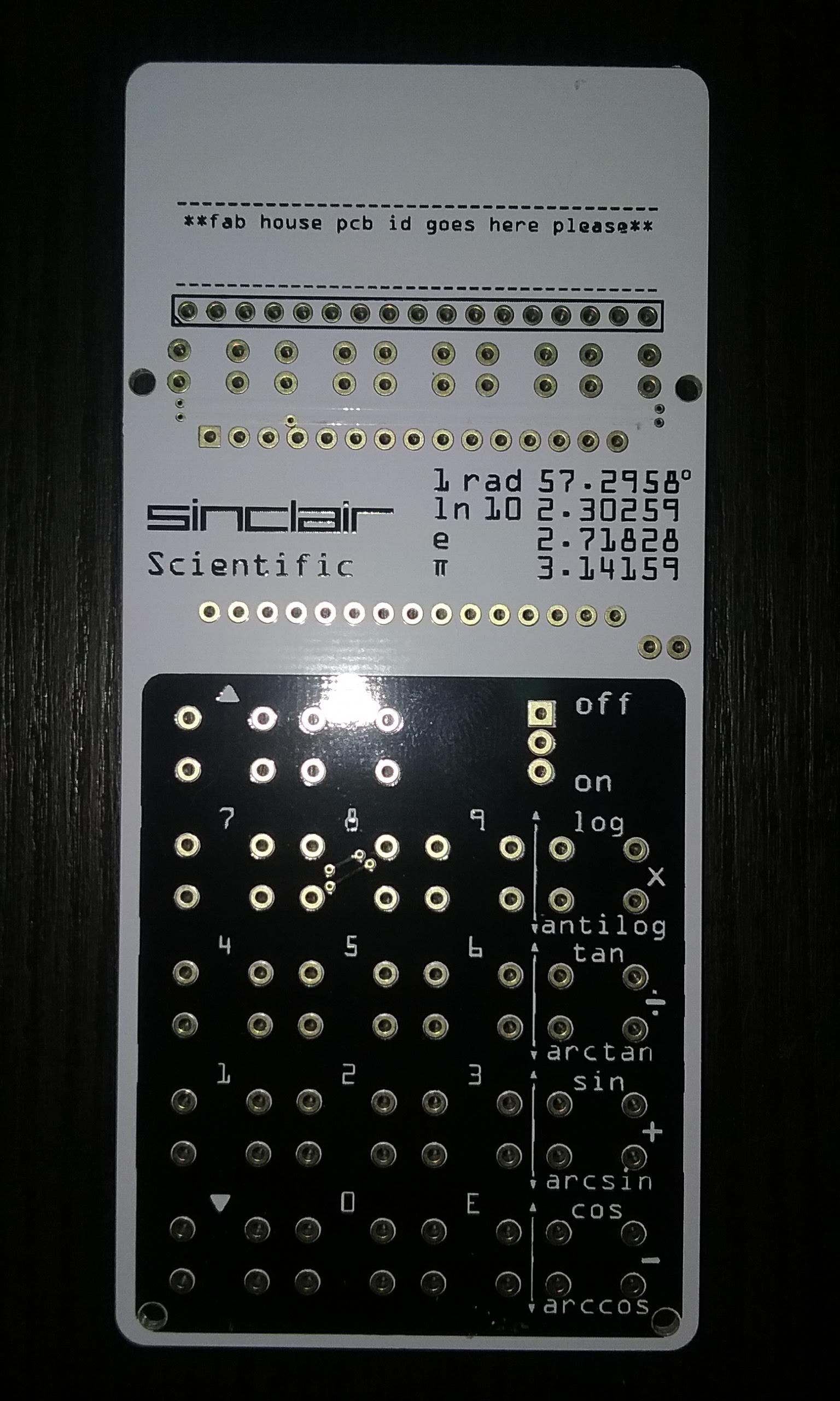
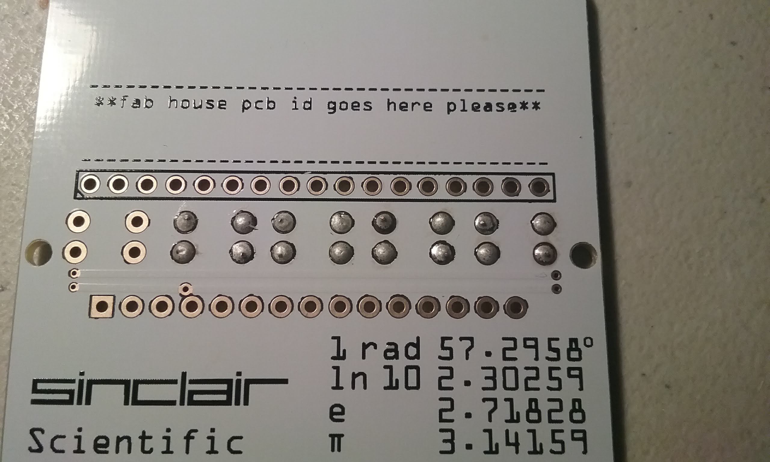
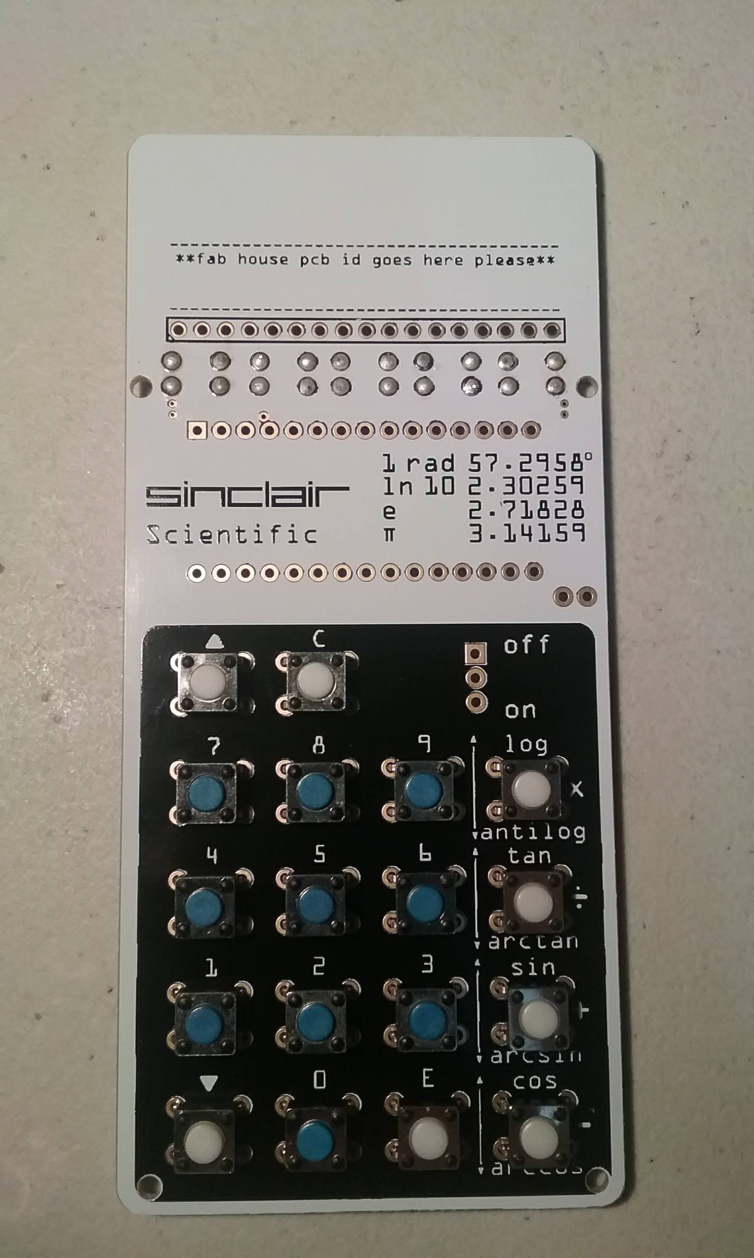
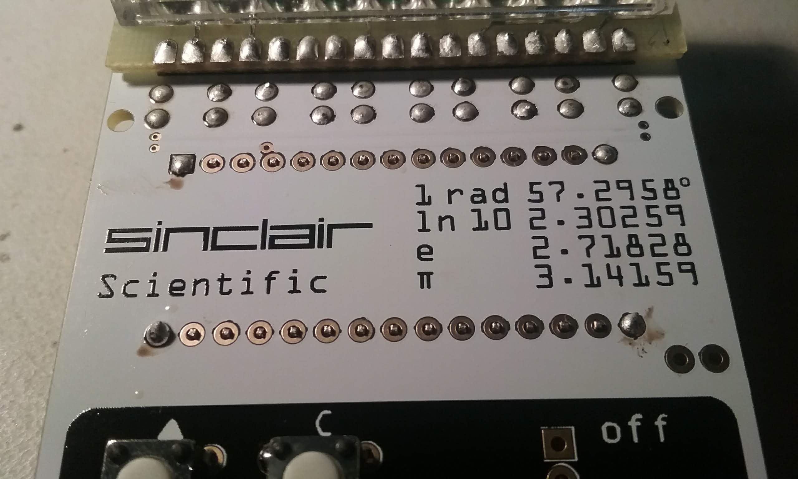
I have opened PCB orders and been thoroughly disappointed before. Everybody can get the Sinclair logo and the text right but the large negative silkscreen in the keyboard is difficult to do correctly. Not this job. The board is perfect. The white soldermask covers the tracks nicely and the black silkscreen is sharp.
The board was plated with Electroless Nickel Immersion Gold (ENIG) .
There is no job number in the area that was dedicated to this marking. It's nowhere to be found. Maybe they do not need to mark the boards, I think to myself.
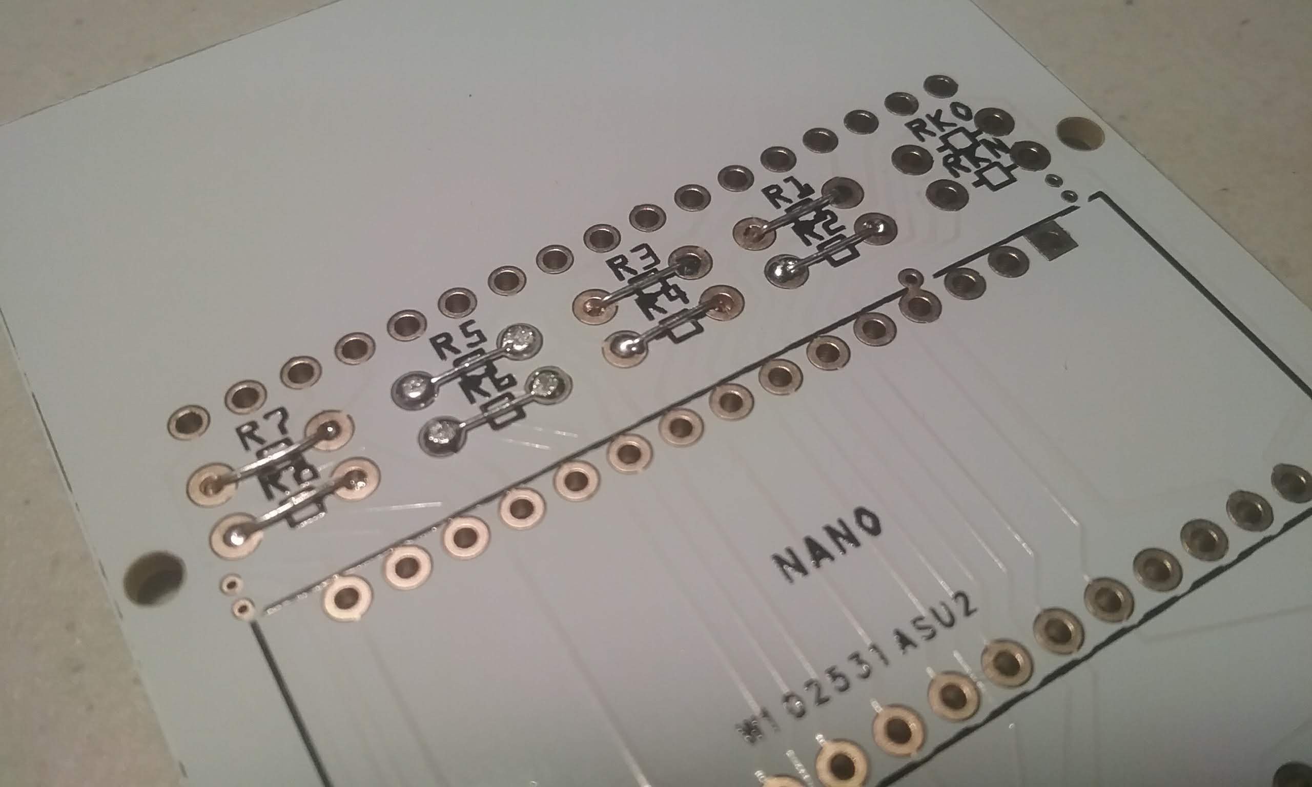
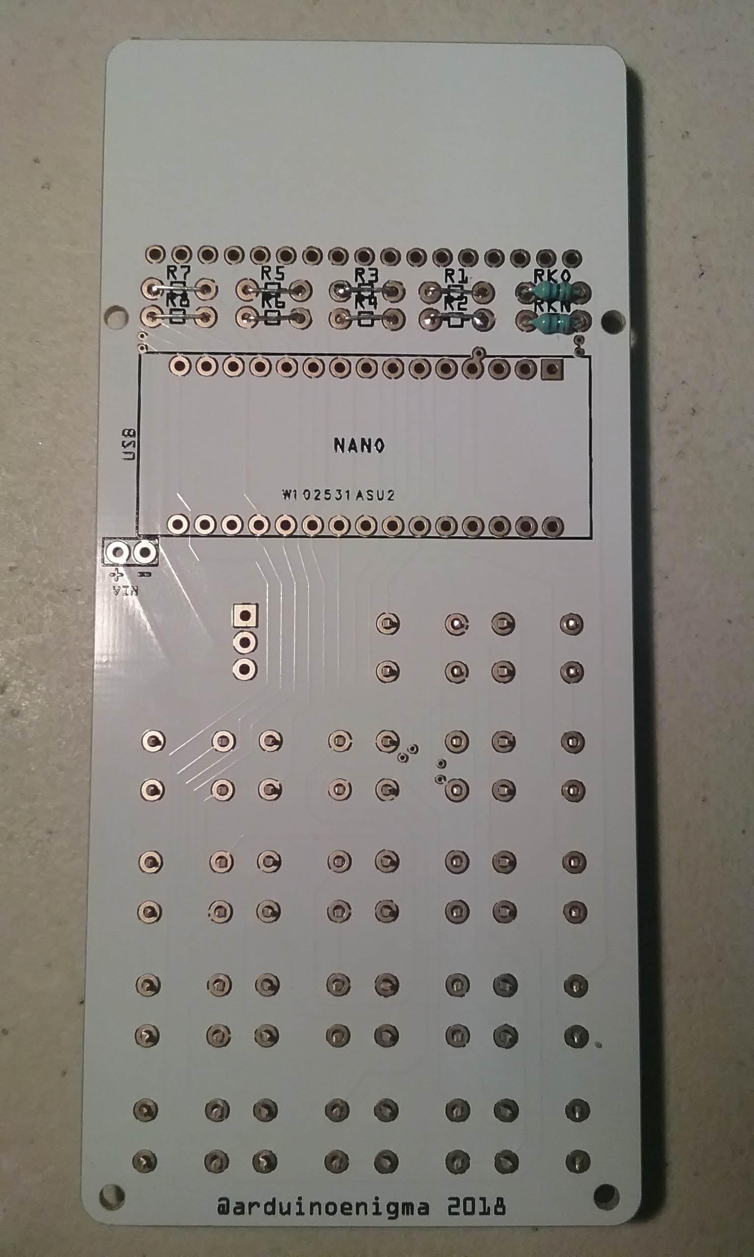
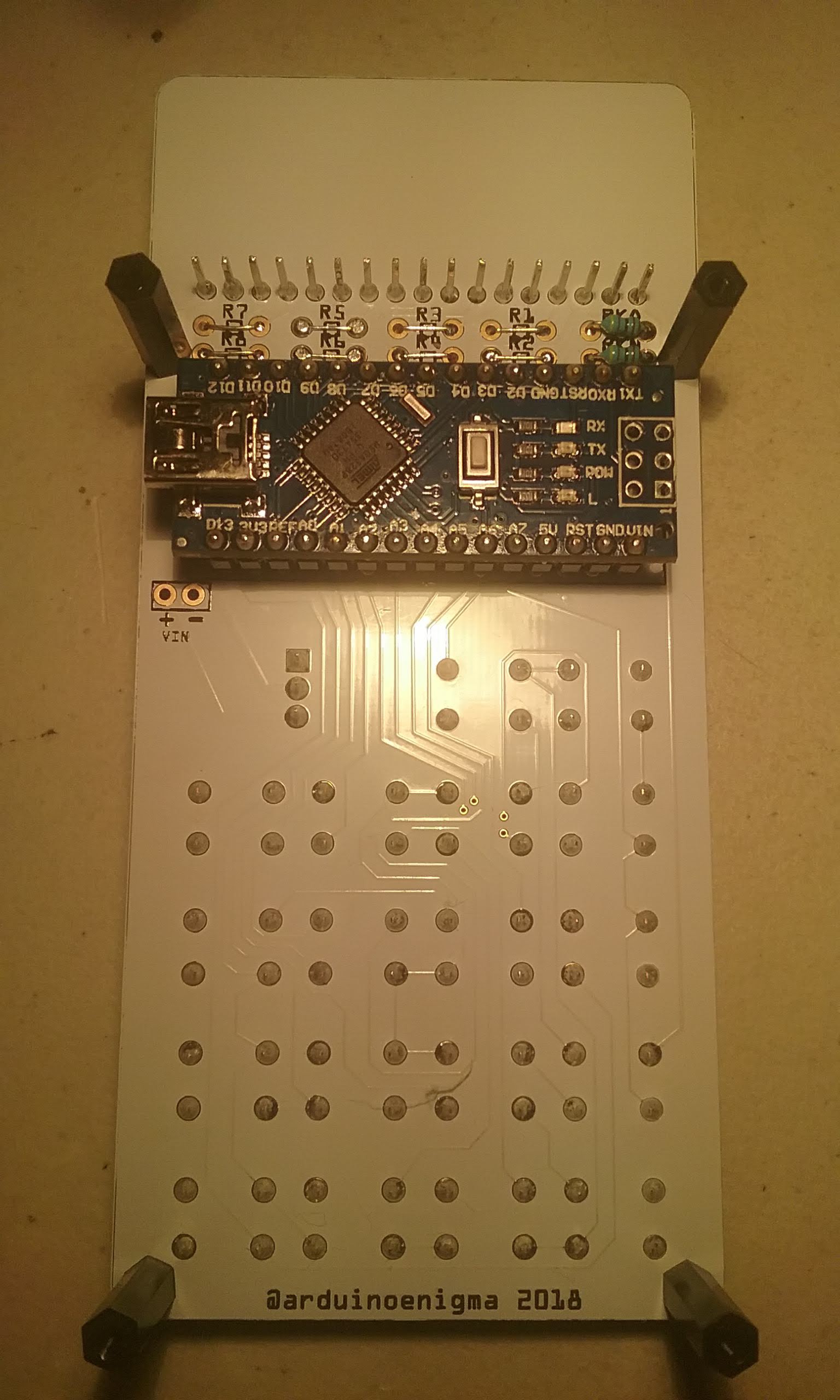
The back of the board also looks good. Then I see it. The job number was placed inside the footprint for the Arduino Nano. Not a bad choice as it will be hidden once the Nano is soldered.

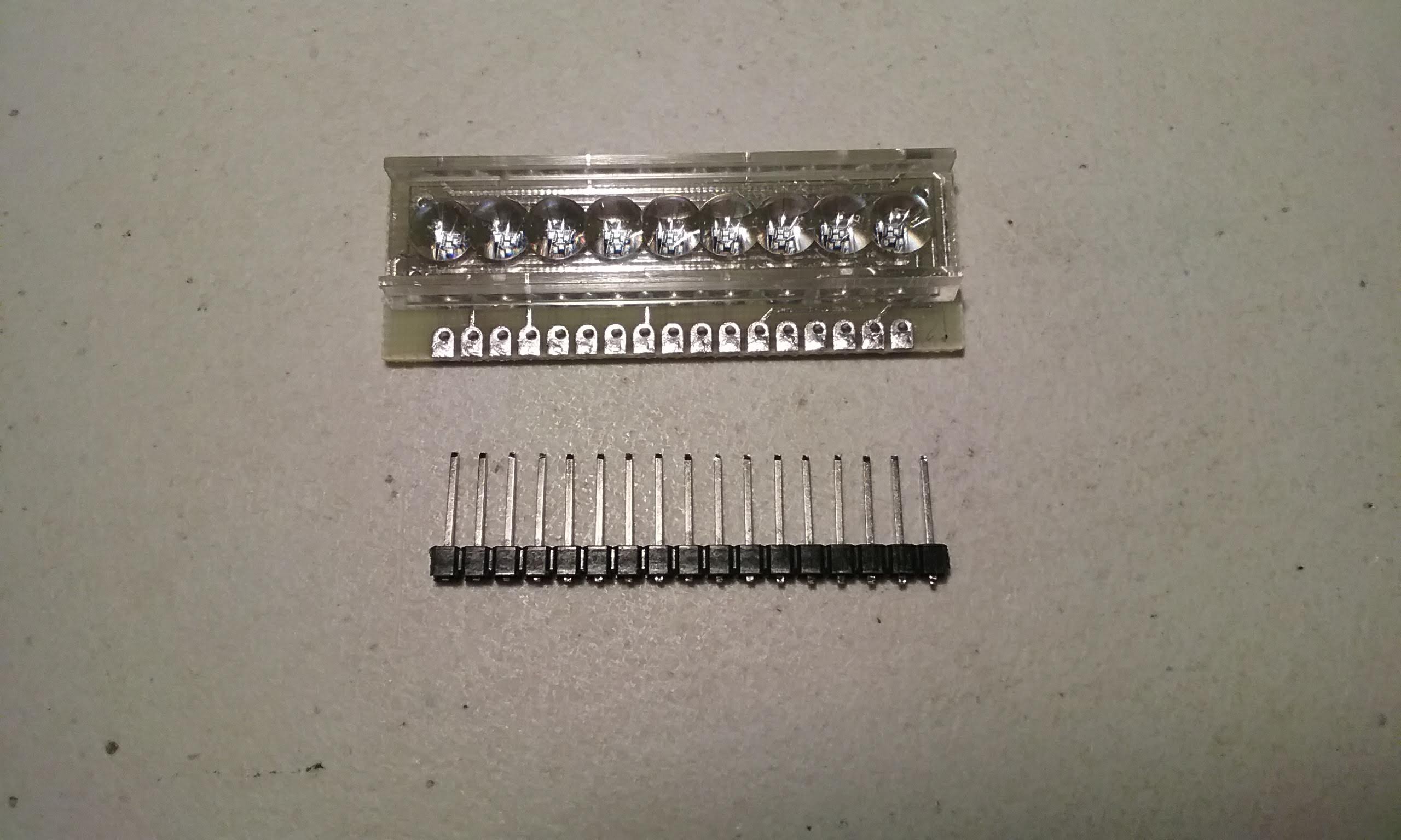
The display comes without headers. I only have 0.1 inch (2.54mm) pitch pins. The display is 2.5mm pitch.
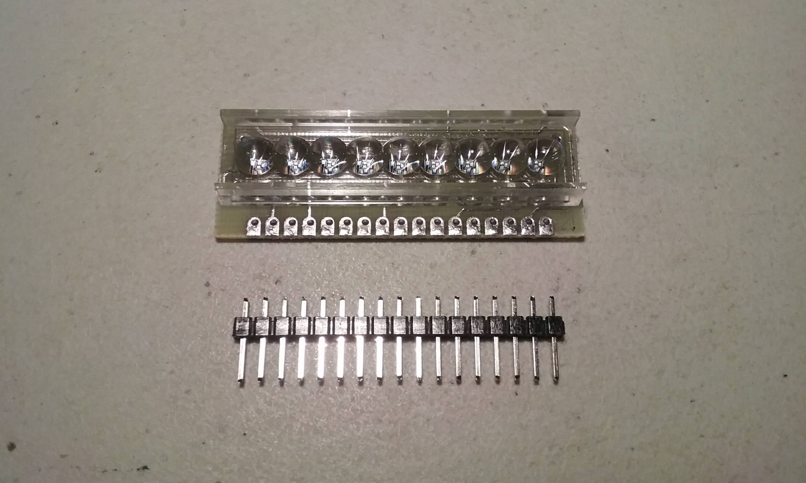
To make it fit, first the spacer is slid down towards the end of the pins.
That allows the other end of the pins to fit into the display. Arrange the pins so they barely protrude from the pads.
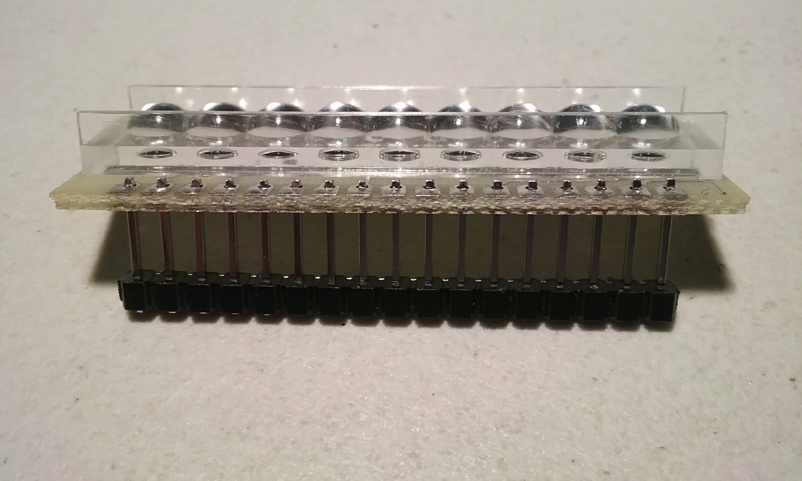
Finally, solder all the pins.
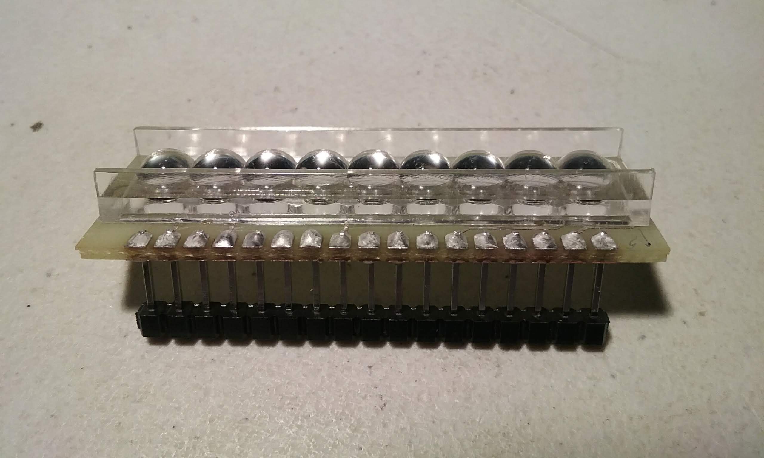
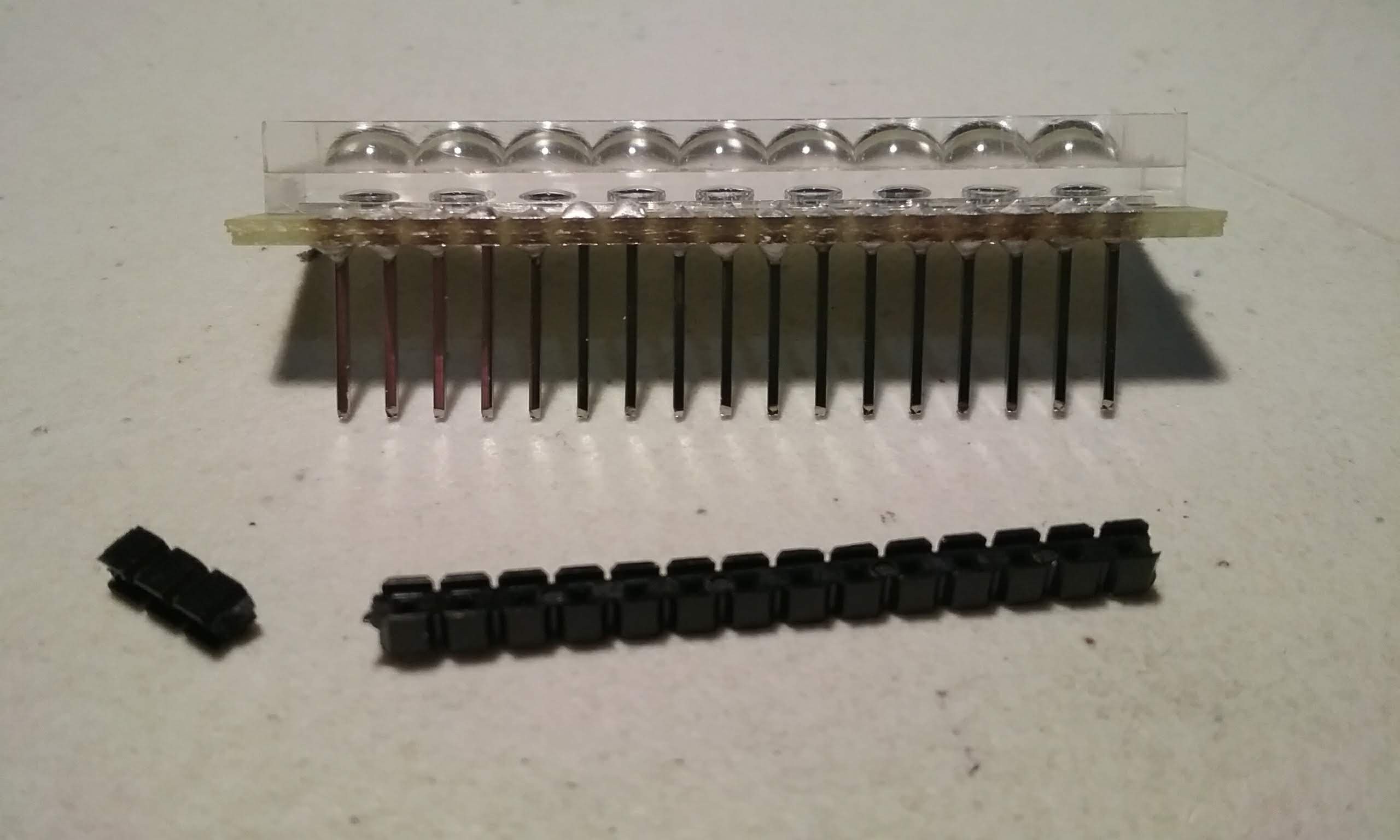
Once that is done, the spacer can be removed.
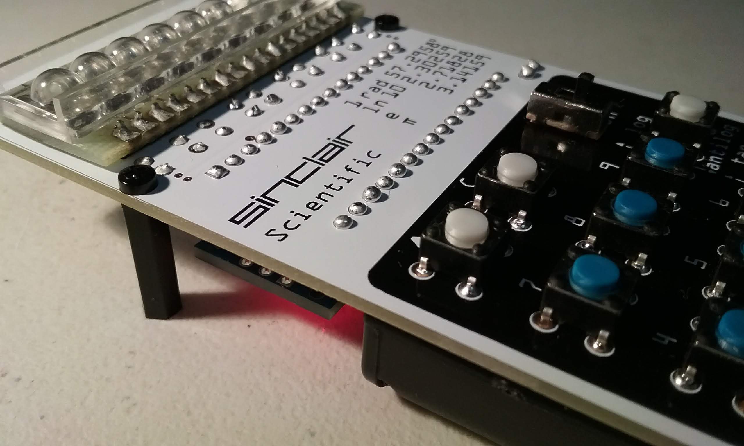
And the display can be test-fitted. Looks good.
The display has been tested in a breadboard using 560R current limiting resistors and the brightness was unsatisfactory. After consulting with other people, it is decided to eliminate the resistors and instead control the current by limiting the time each digit is turned on.
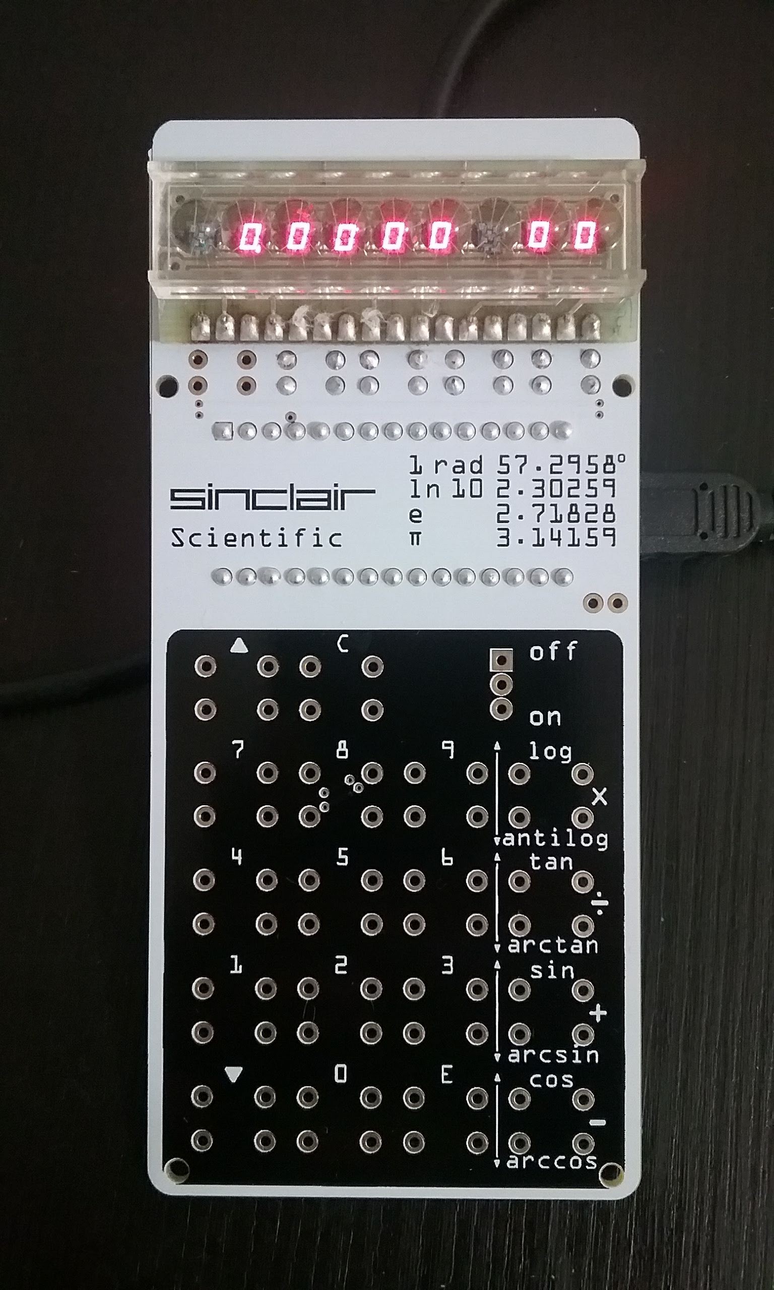
The Arduino is soldered and powered up and it works. The display works reliably as long as the time each digit is turned on is limited. Each digit is ON for 400uS and off for 8x400us (3200uS / 3.2ms)
Now that we know that this solution works reliably, we can finish assembling this calculator.
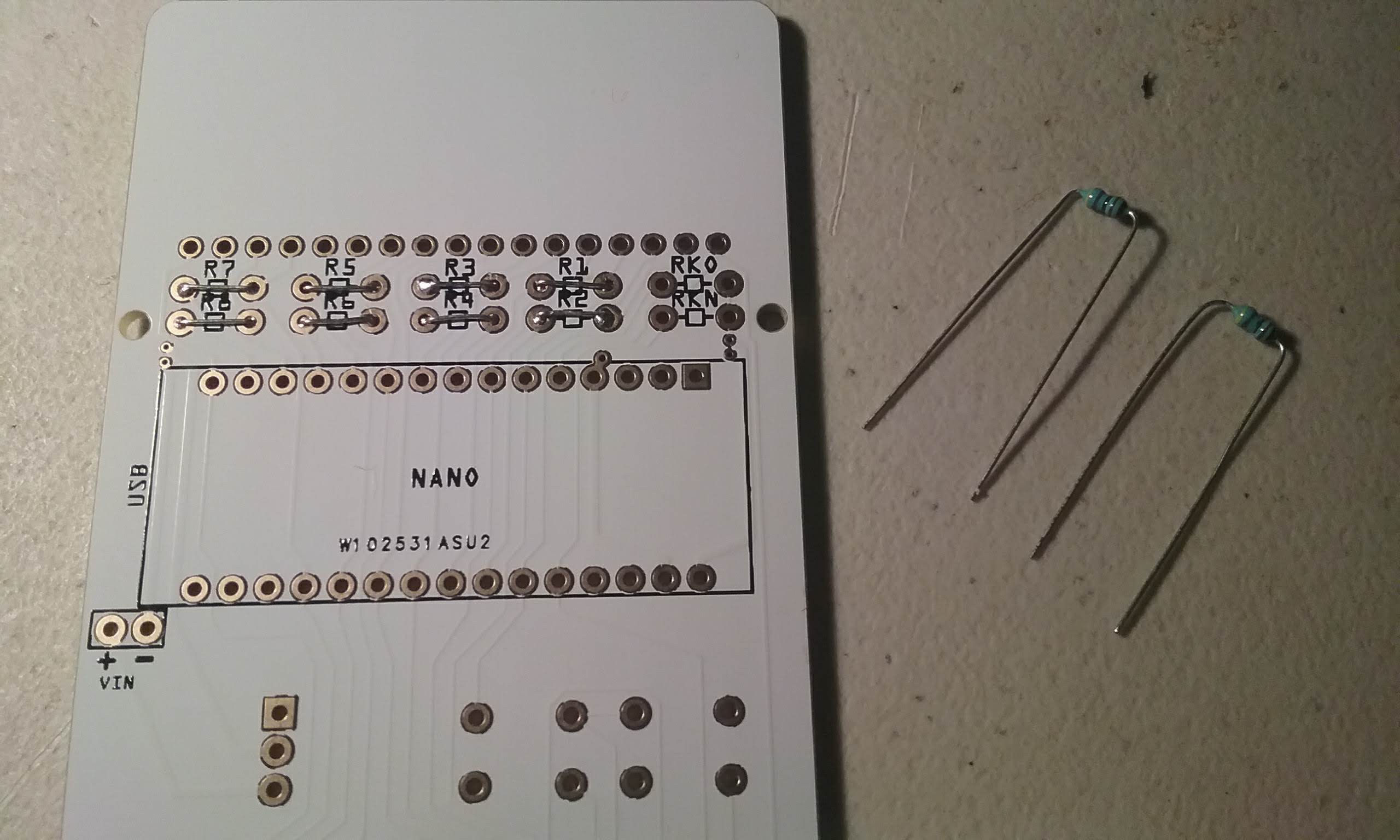
To assemble a calculator from scratch, start with a bare PCB:
Use the legs of a resistor to make the shorting links. Each leg will produce two links. Two resistors will produce the 8 links needed.
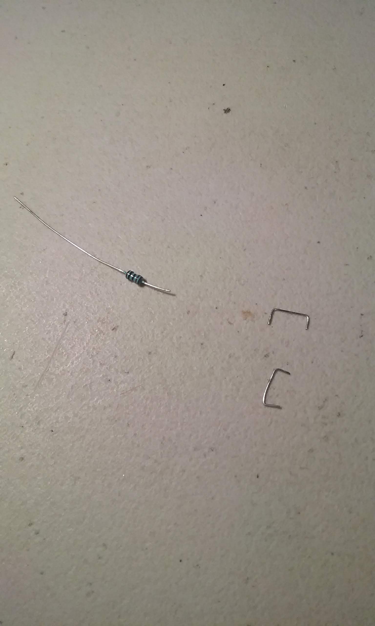
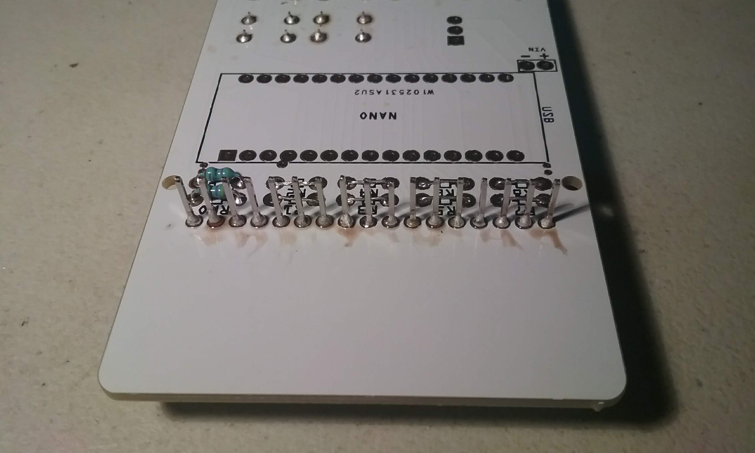
Insert the links from the top and use a backer piece to hold it in place while the board is flipped and the link is soldered.
Finish soldering all 8 links. Do not put shorting links in RKO and RKN.
This is how the links look from the bottom.

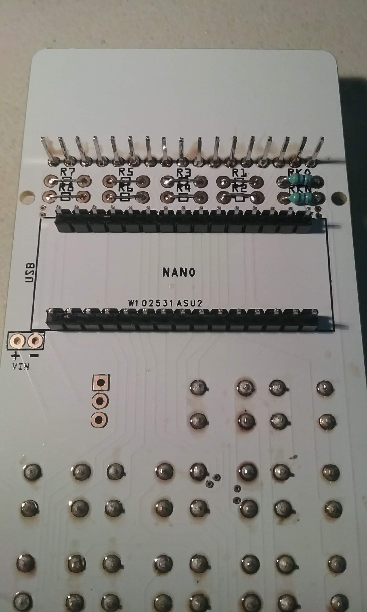
Next, prepare the 4.7K resistors used in RKO and RKN.
Insert them and flip the board.

Solder and trim the legs.
Next install the keys, make sure the blue keys go in the numbers and the white ones in the rest.
After checking the button alignment, flip the board and solder the buttons, one column at a time.
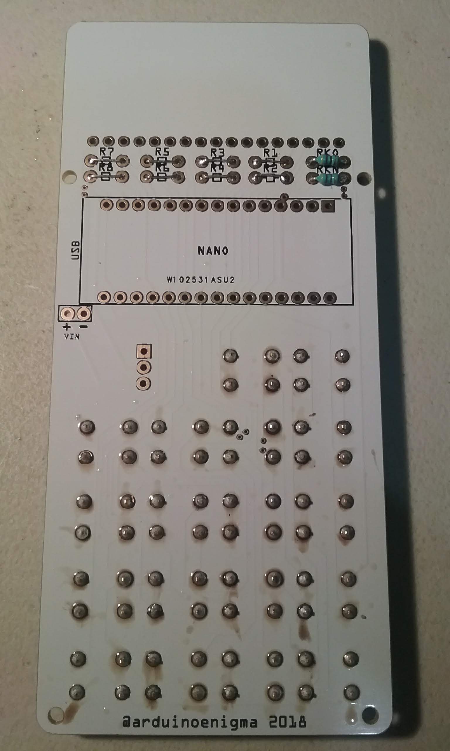
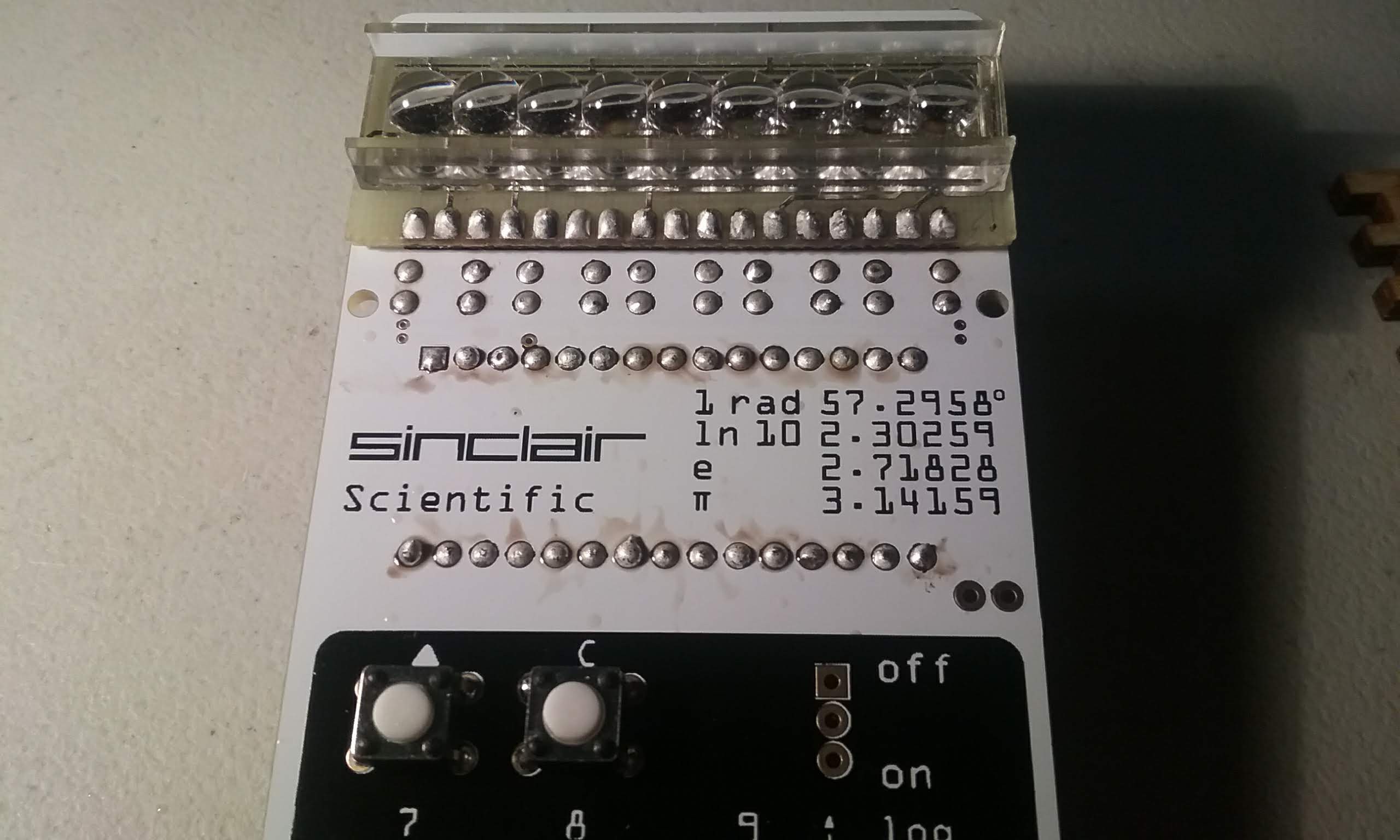
After soldering all the keys, the board will look like this:
Insert and solder the bubble LED module.
Then insert the headers that came with the Arduino. Insert the long side of the pins in the board.
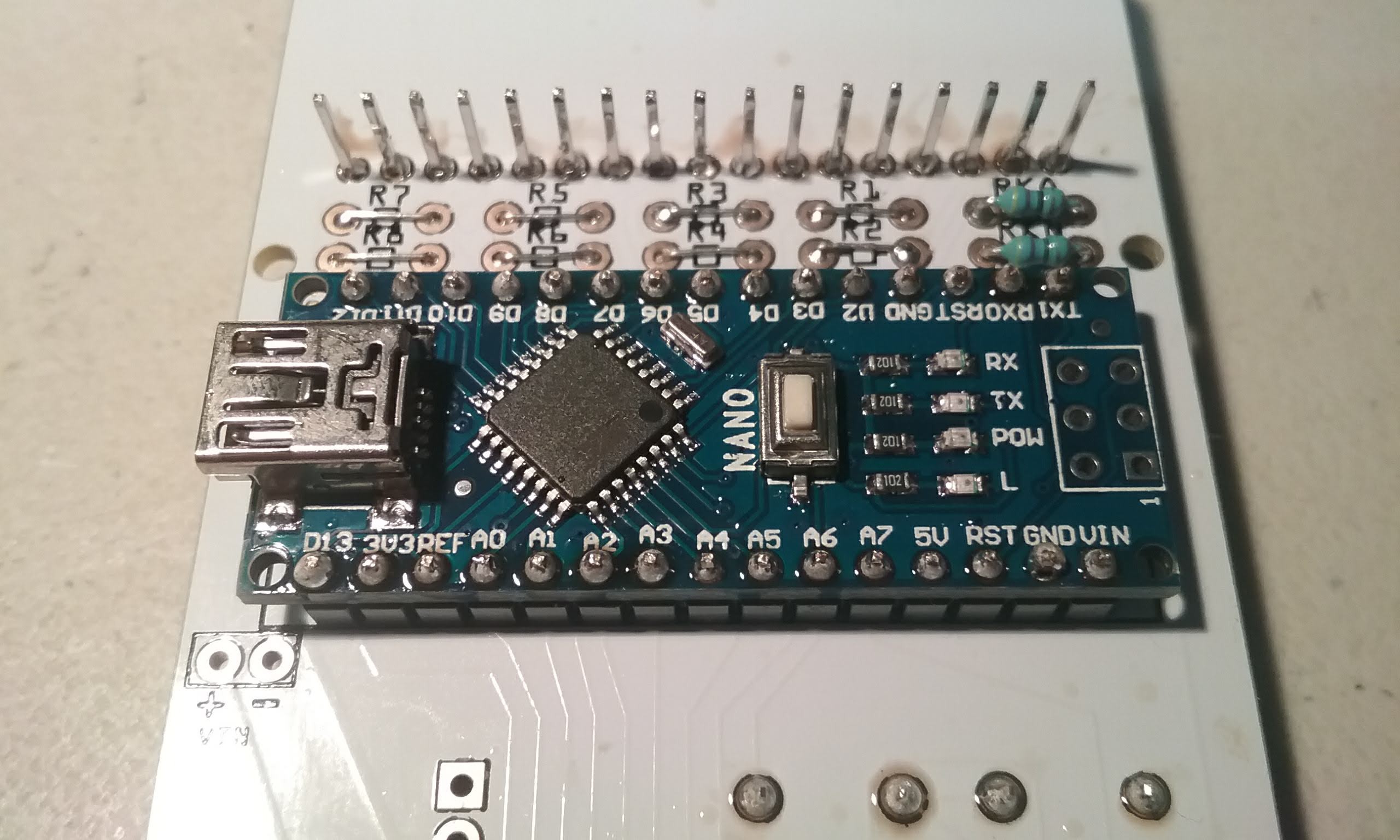
Install the Arduino, ensure the USB connector is on the same side as the legend on the board.
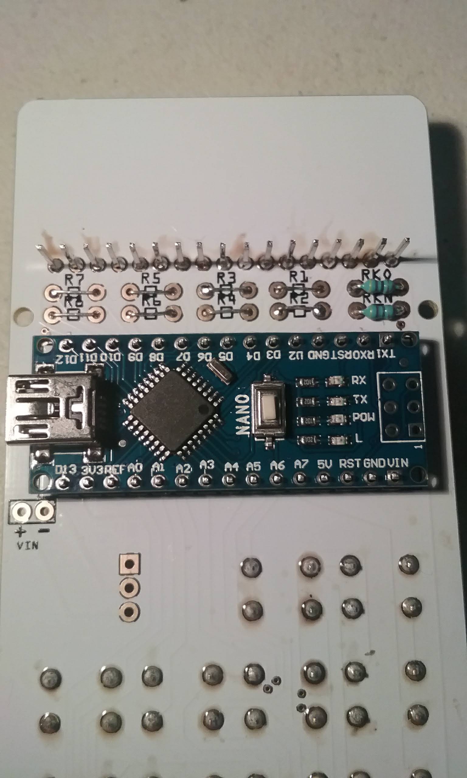
Solder the four corner pins.

Then finish soldering the rest of the pins in the Arduino.
Flip the board over and push the long pins until they barely protrude.
Solder the four corners:
Then finish soldering all the pins.
Finally, install the standoffs and clean the flux with a water soaked Q-Tip.
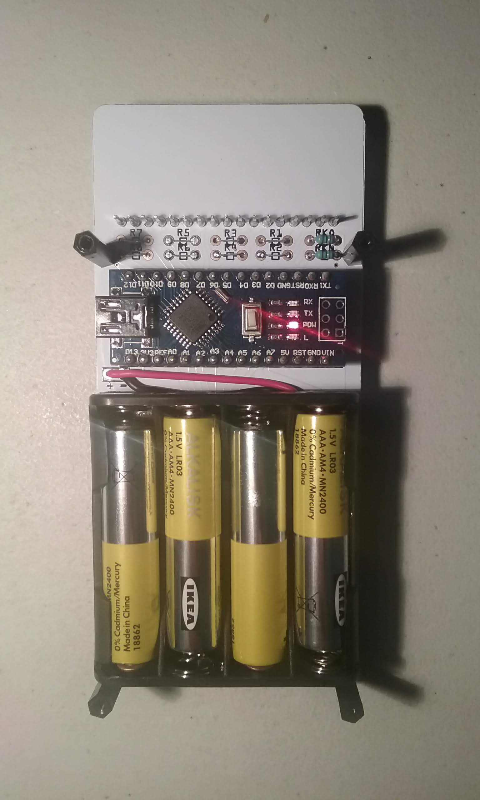
Here is the board with the remaining components, the power switch and the battery pack soldered.
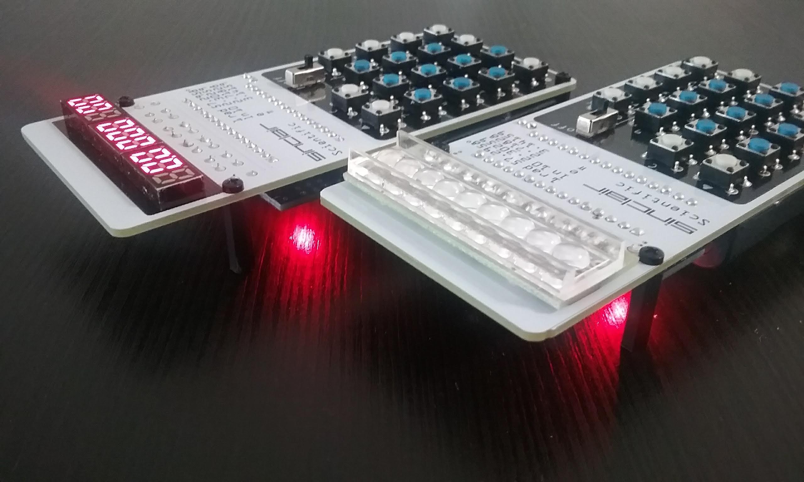
Here are the modern and the bubble LED version side by side.
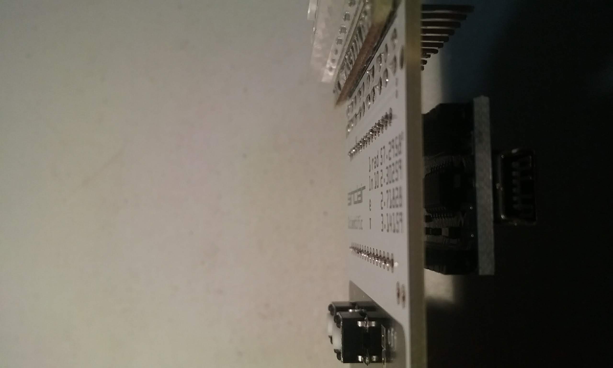
This is what the bottom of the board looks like:
A corner shot:
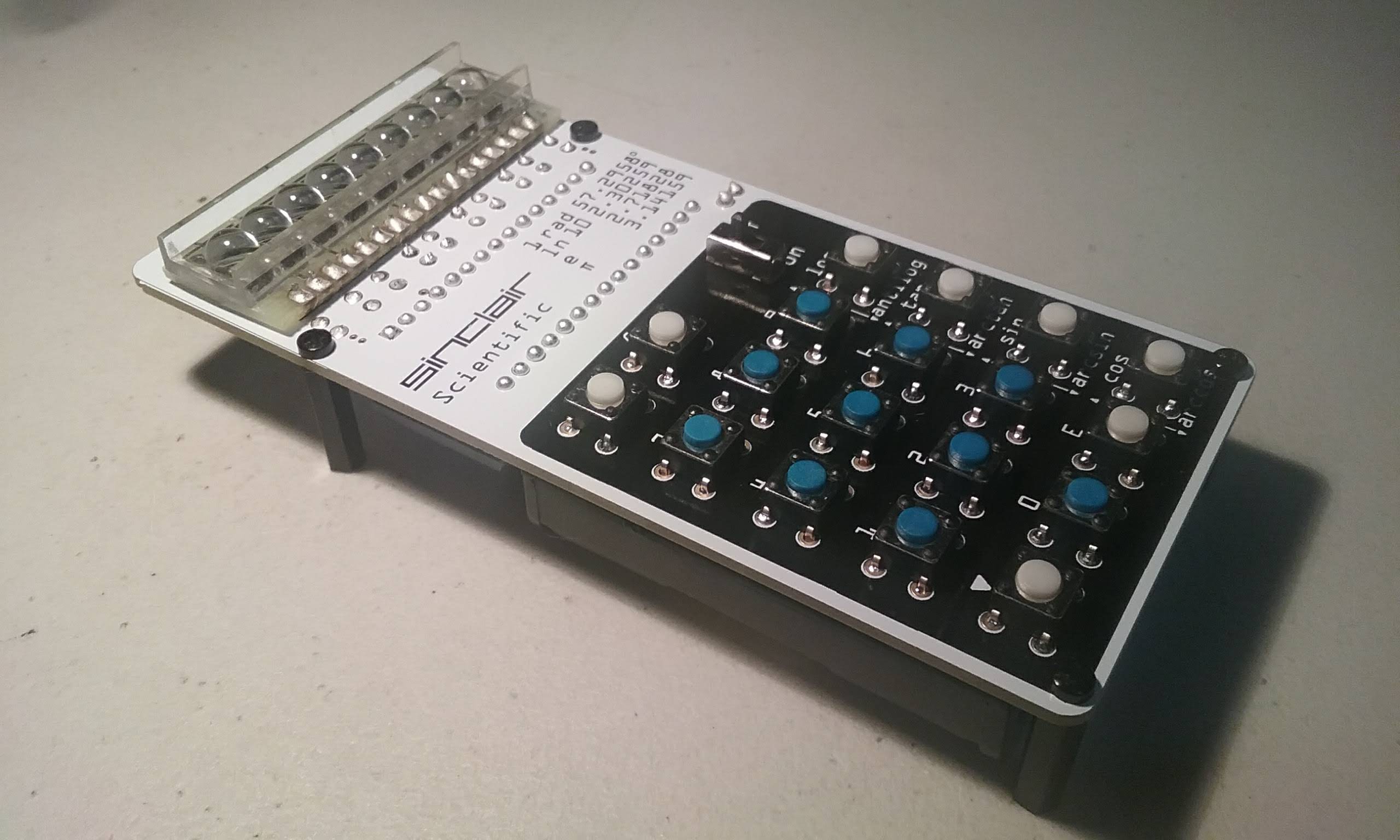
Here is the finished product. I am very pleased with the quality of the boards PCBWay.com manufactured. The soldermark is a very brilliant White and the Black silkscreen is very sharp.

.
Discussions
Become a Hackaday.io Member
Create an account to leave a comment. Already have an account? Log In.
The BEST Project Ever!! A tour de force, a virtuoso performance by Arduino Enigma!
Are you sure? yes | no