 rawe
raweNimak ZS 161
Specs
Manufacuter: Nimak Schweißmaschinen, still in business; they build welding equipment for robot mounts nowadays: http://nimak.de/
Device: ZS 161
Nominal power: 2 KVA
Supply power: 11.3 KVA (yes, it blows "C16" fuses sometimes)
Primary voltage: 380V, connected to two 220V phases of a three-phase grid.
Secondary voltage: 2.4 V
Secondary short circuit current: 7.7 kA
Built: ??? "made in west-germany" / 4 digit postal code /220V device= between 1961 and 1987
Symptoms: Does not weld, does not make any sound, gets warm, damaged supply cable, pot knob missing
Inspection
The damaged supply cable was obvious and an easy fix: Shorten supply cable by 10 cm.
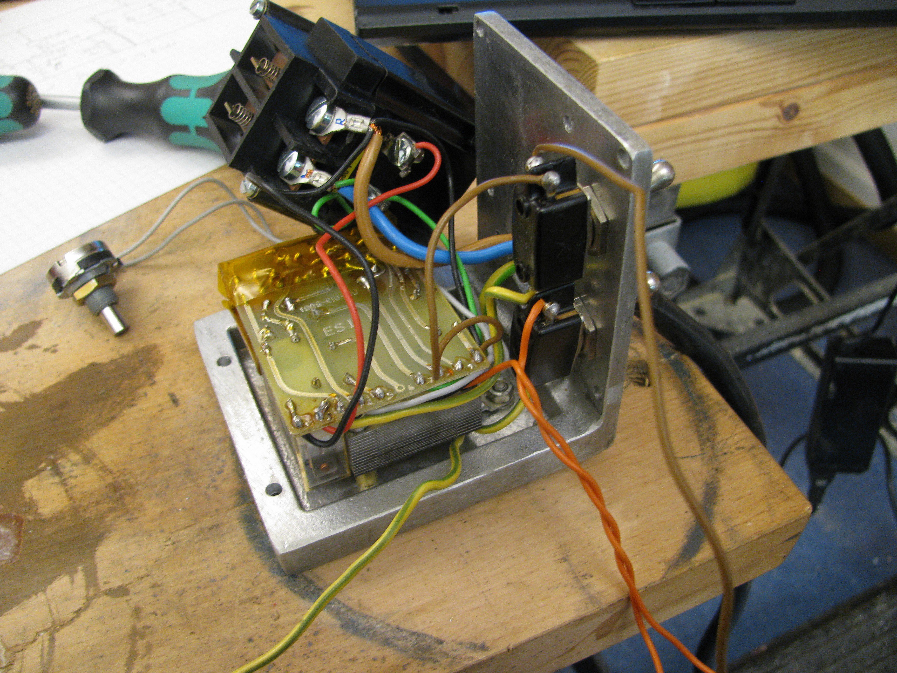
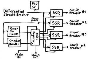
The unit contains a small transformer that powers a control board. That control board switches a big relay that powers the welding transformer. Simple, huh?
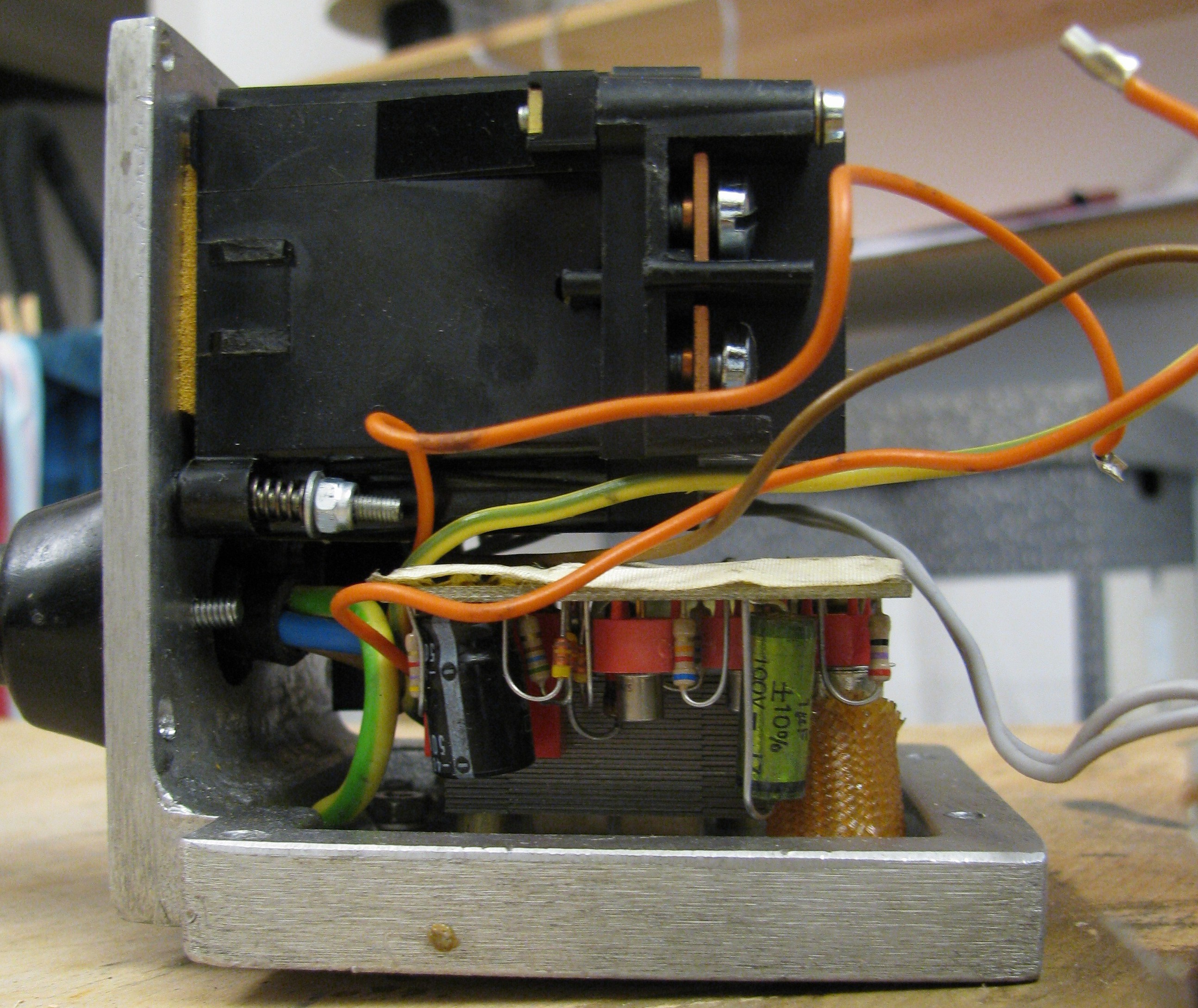
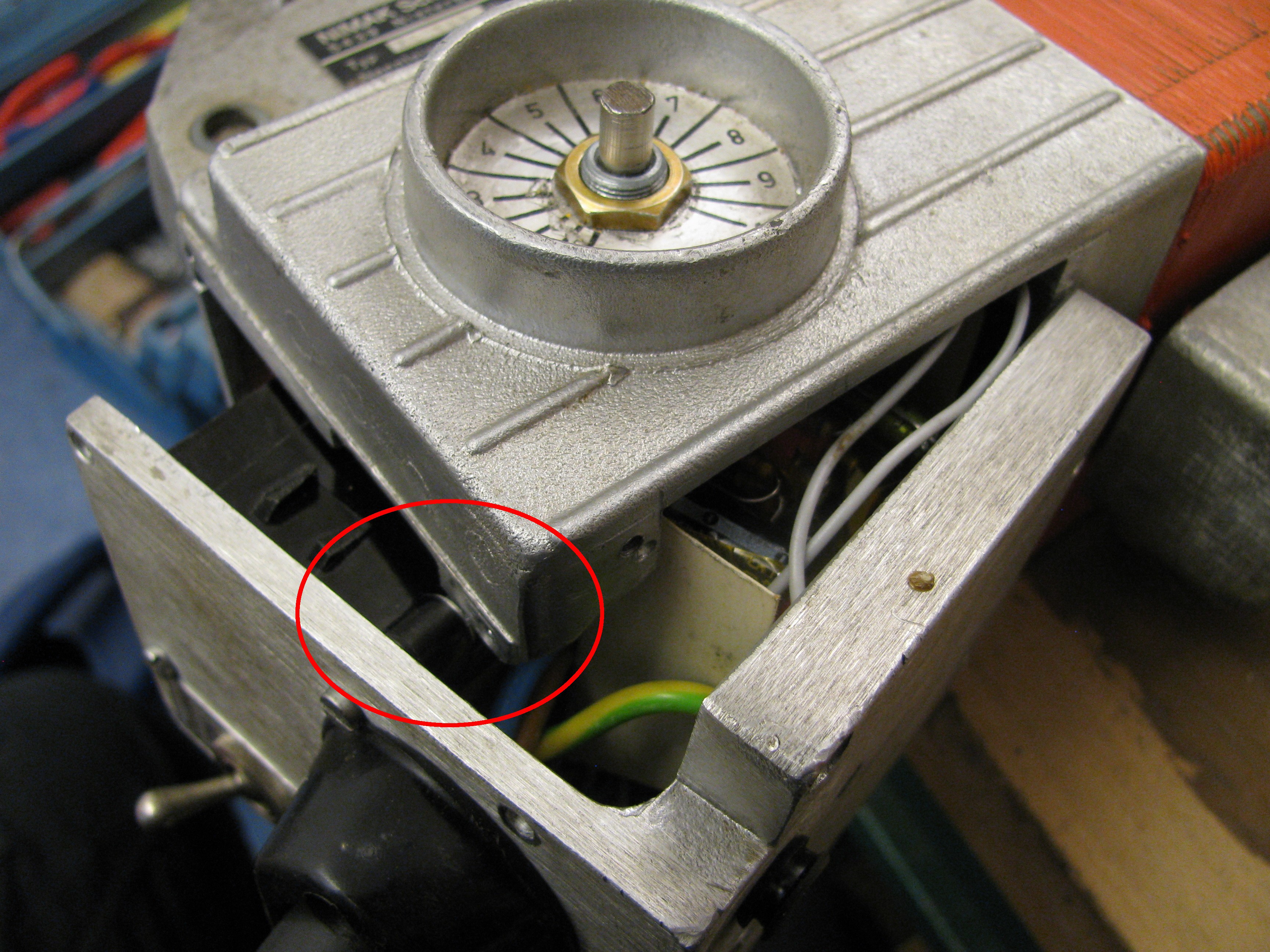
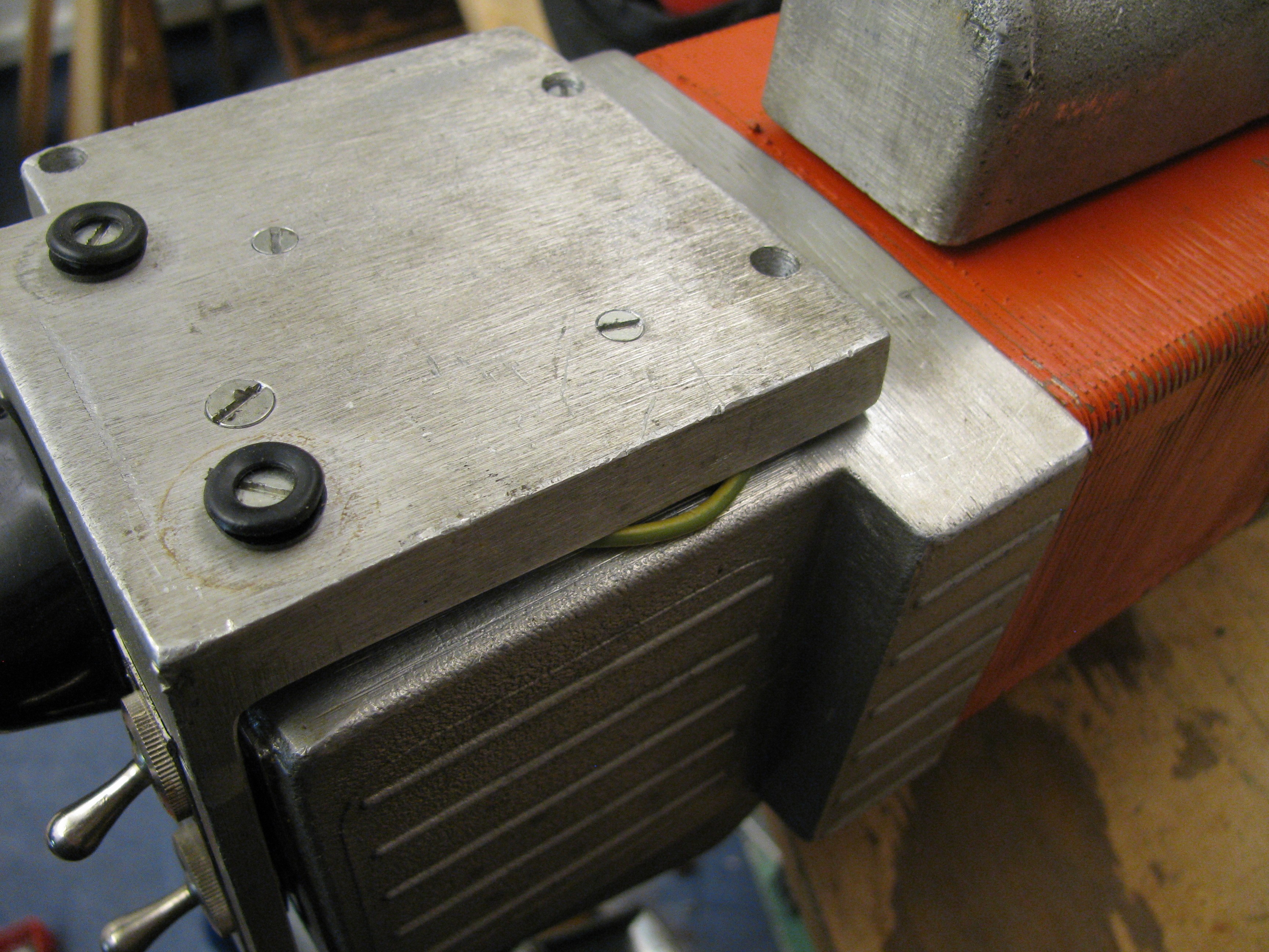
Disassembly (and reassembly) is a pain. How to access these nuts without special tools?
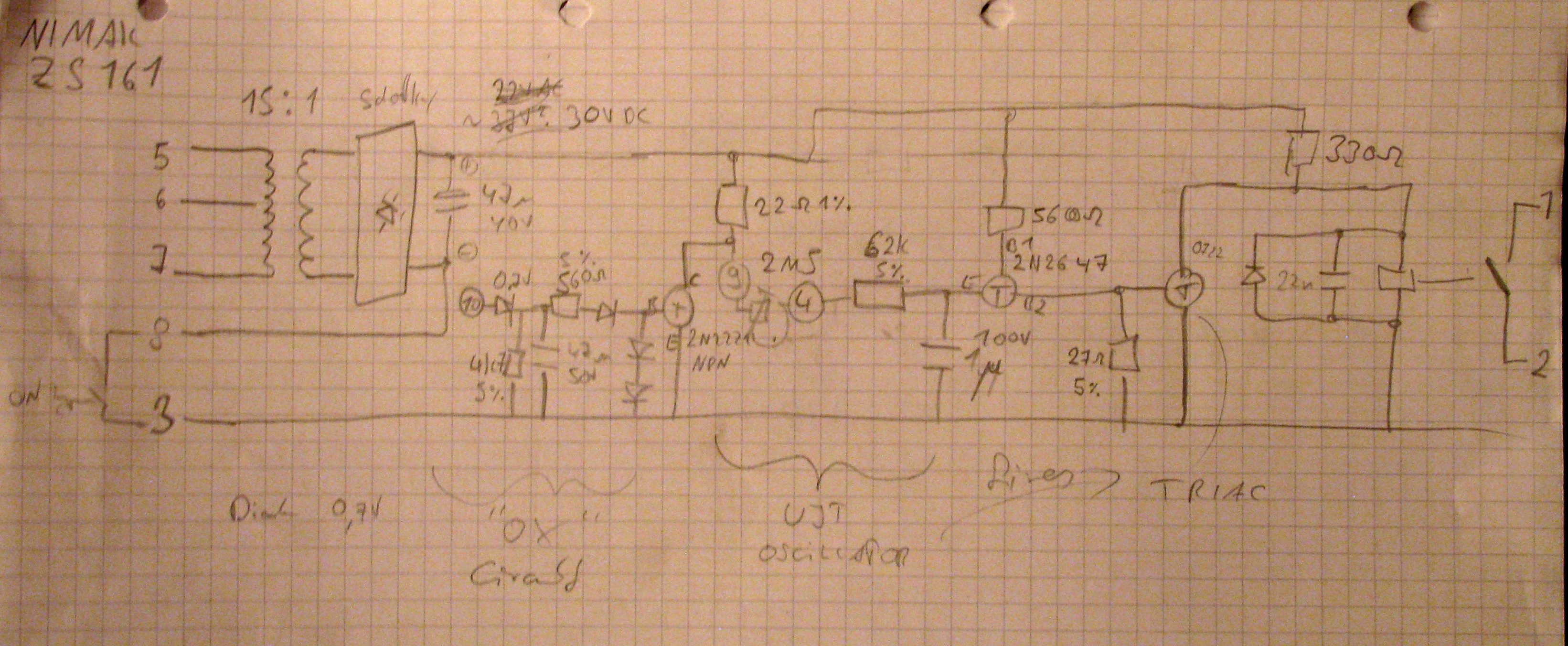
The main triac is not labeled with useful data, so I have no idea what exact type it is. The principle of operation is as follows:
- A normally open switch in the handle (activated on pressure of the big "C" clamp) connects the circuit after the bridge rectifier/filter cap
- the relay on the PCB gets powered, it connects the main relay to mains, that relay powers the welding transformer
- an unijunction transistor (timing controlled by 2.5 meg pot on side of device) oscillator ends its first period and triggers a triac that shorts out the relay coil, welding stops.
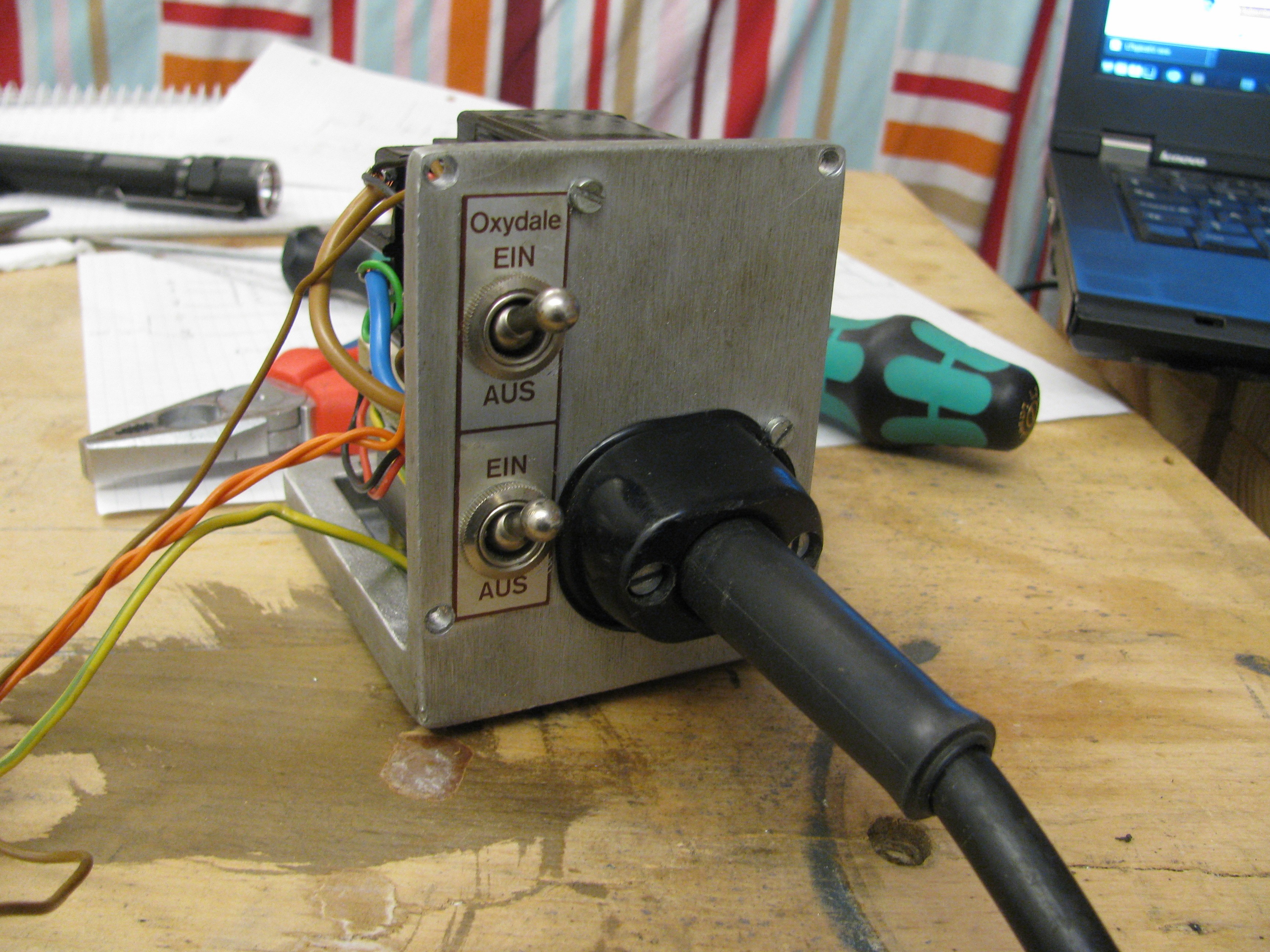
An additional "anti oxidation" circuit seems to block (?) the unijunction transistor oscillator based on a switch setting and the voltage on an additional welding transformer winding. As I am no spot welder expert, it would be great if someone could tell me the use of this switch/circuit part.
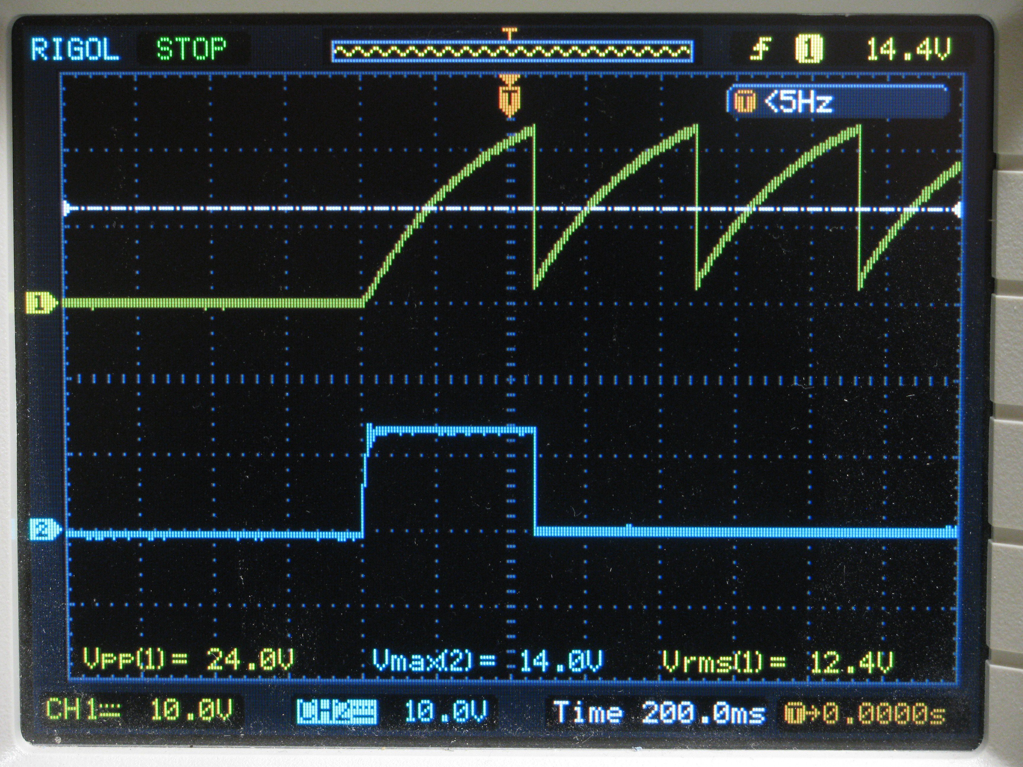
The scope shot below shows the UJT oscillator (yellow) and the relay coil voltage (blue):
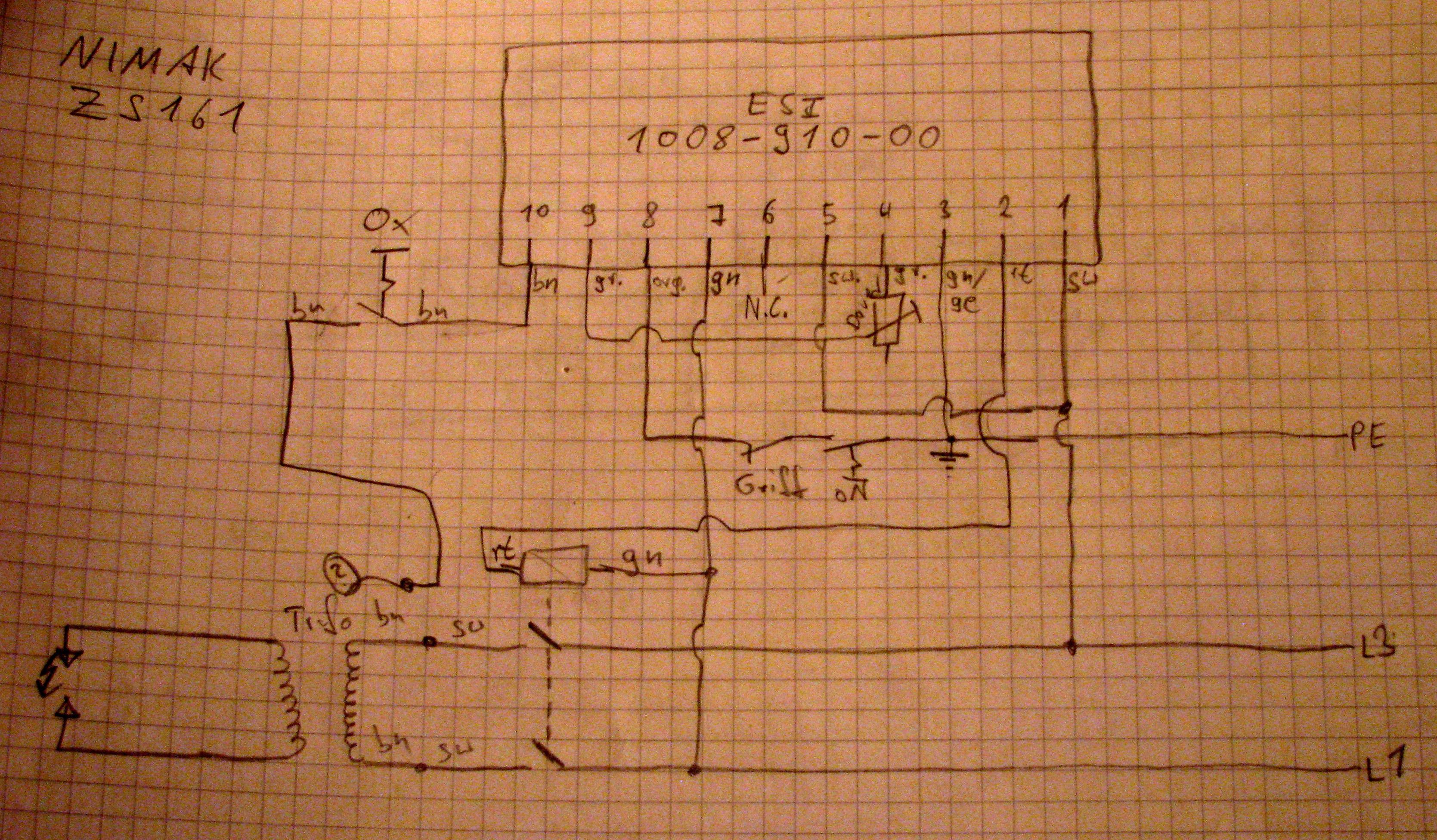
Long story short, here is the read out schematic:
Control PCB:
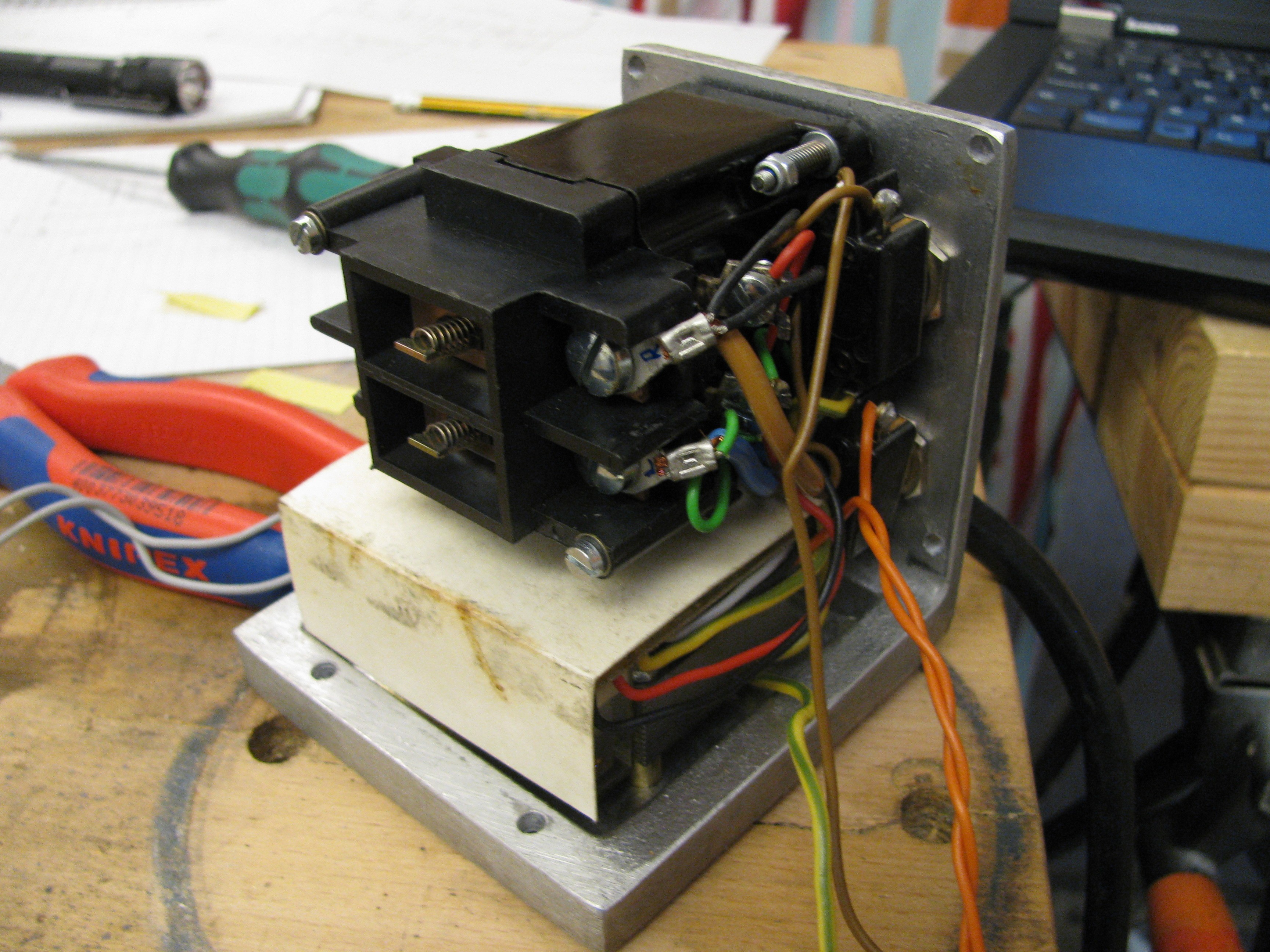
In device cabling:
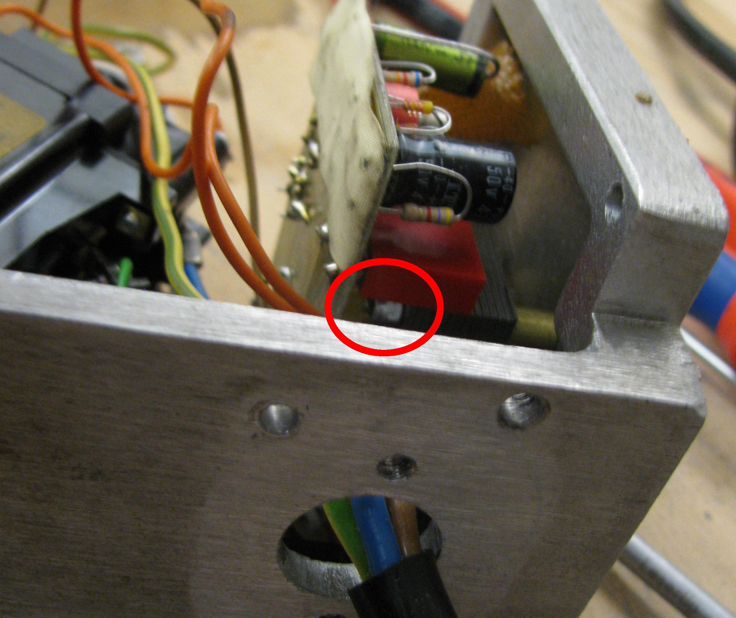
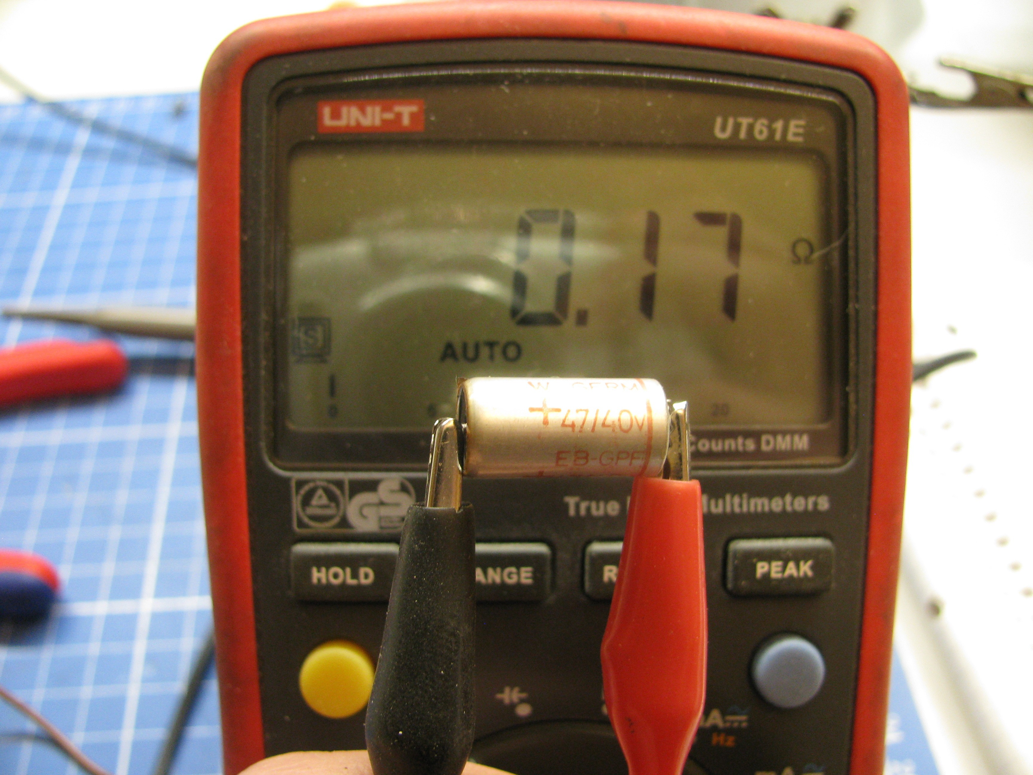
Guess which part is the broken one....
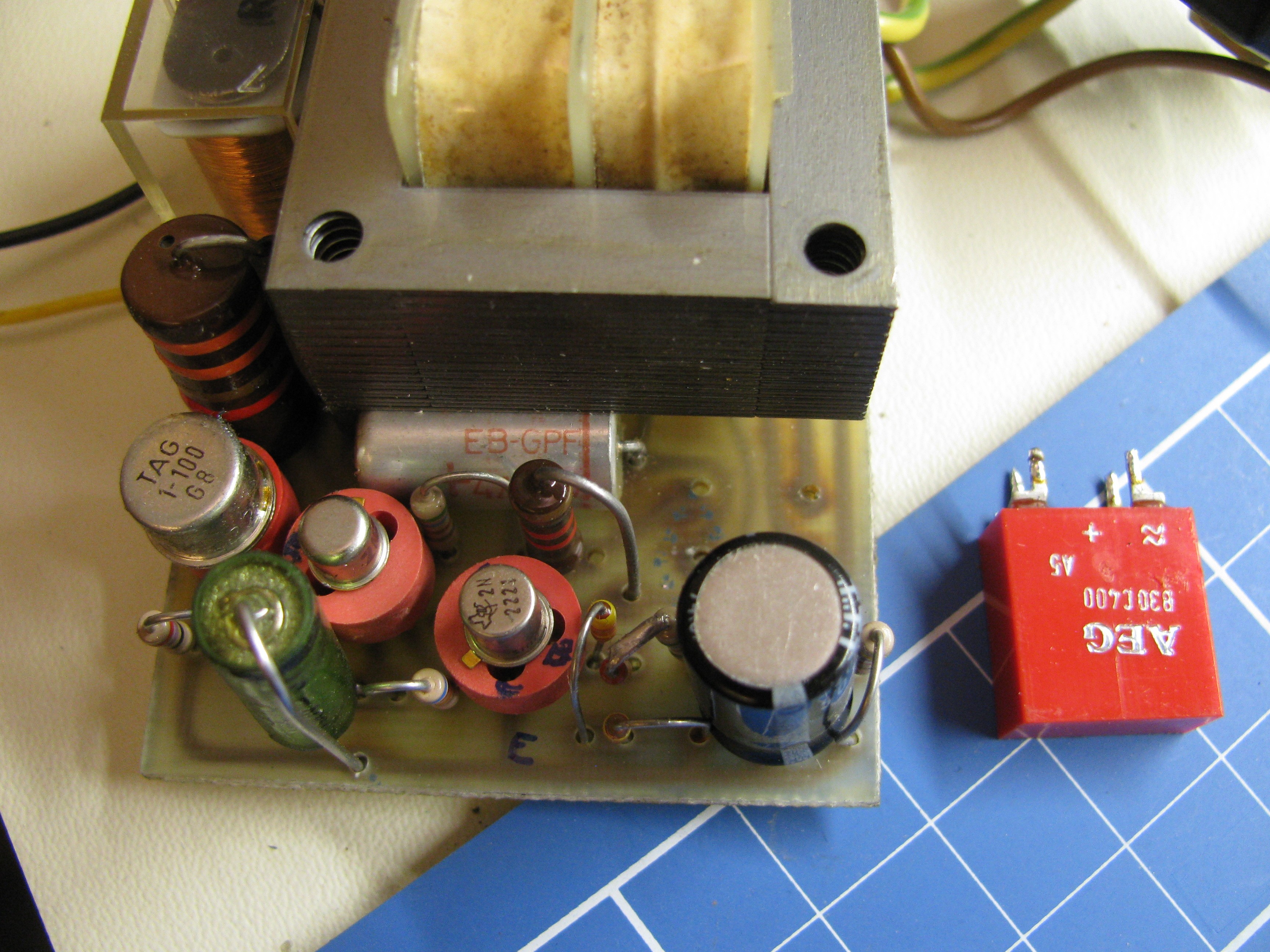
Yes! It's the main filter cap after the bridge rectifier that is the worst-accessible part in this device:
Reassembly
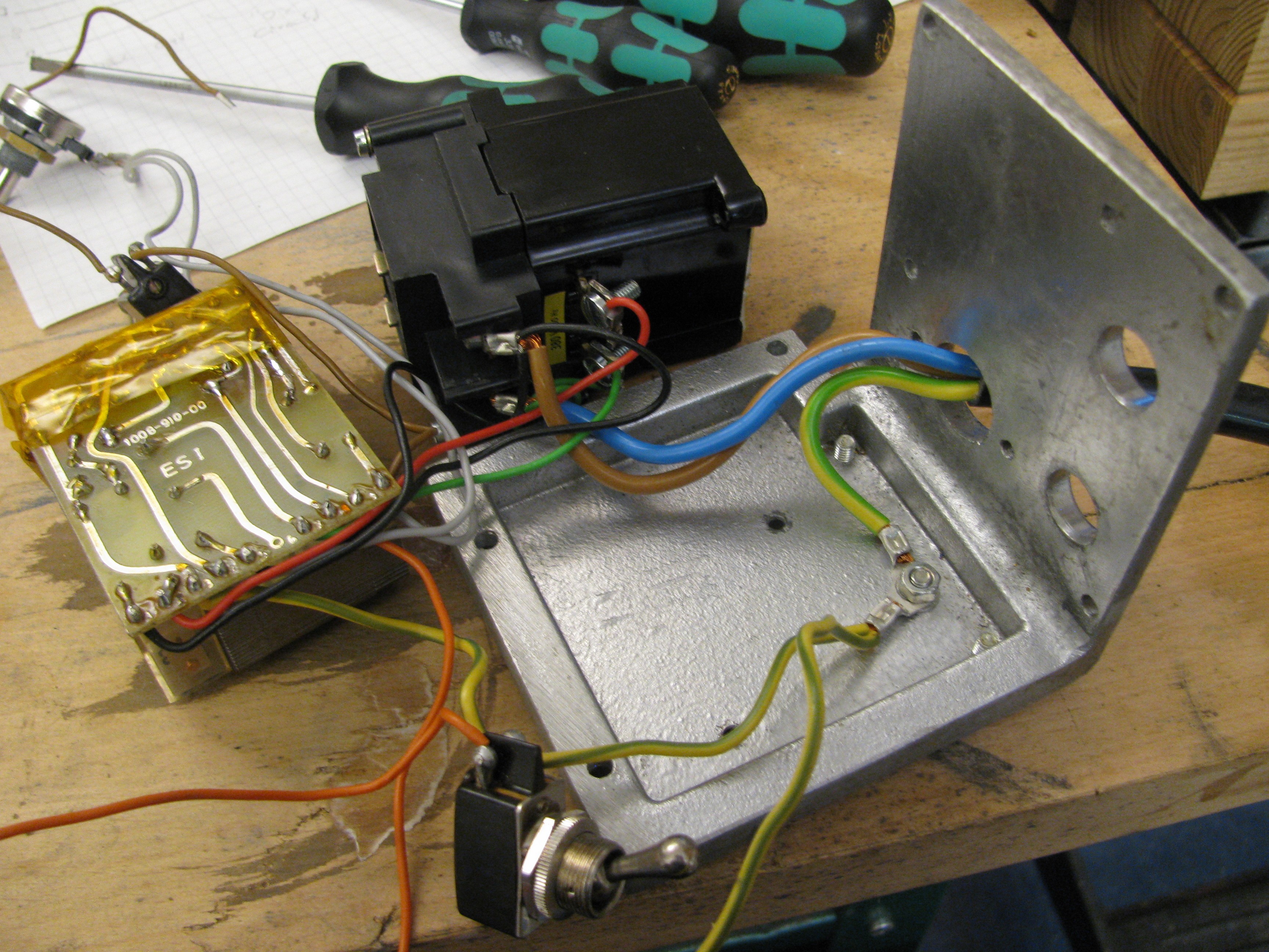
The big relay got foam on the enclosure-facing side and is mounted with springs on the screws to dampen vibration. The foam dissolved over the years, so it was replaced.
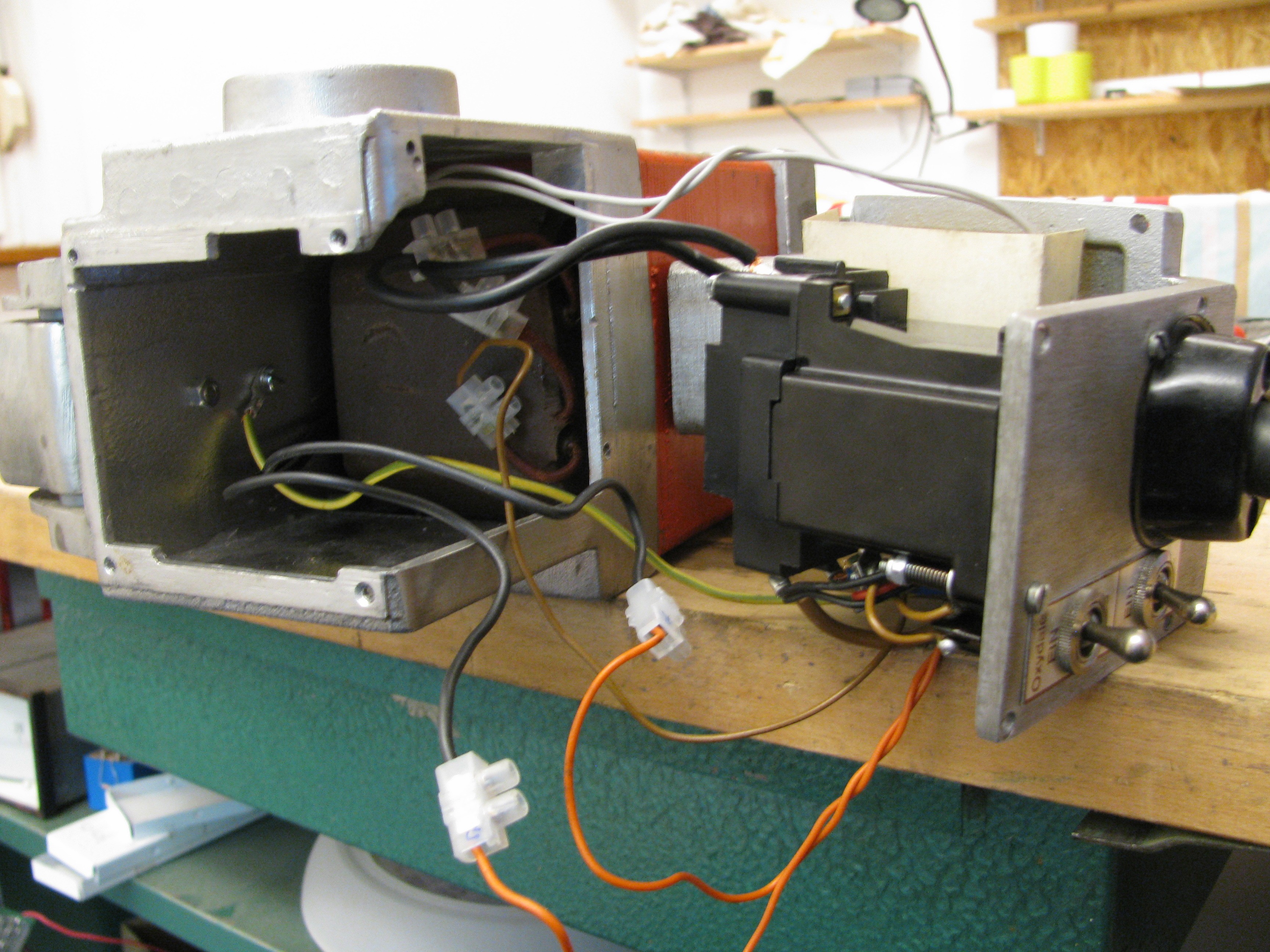
Shifting the L-shaped enclosure part in is a bit tricky...
Cables do not want to stay inside...
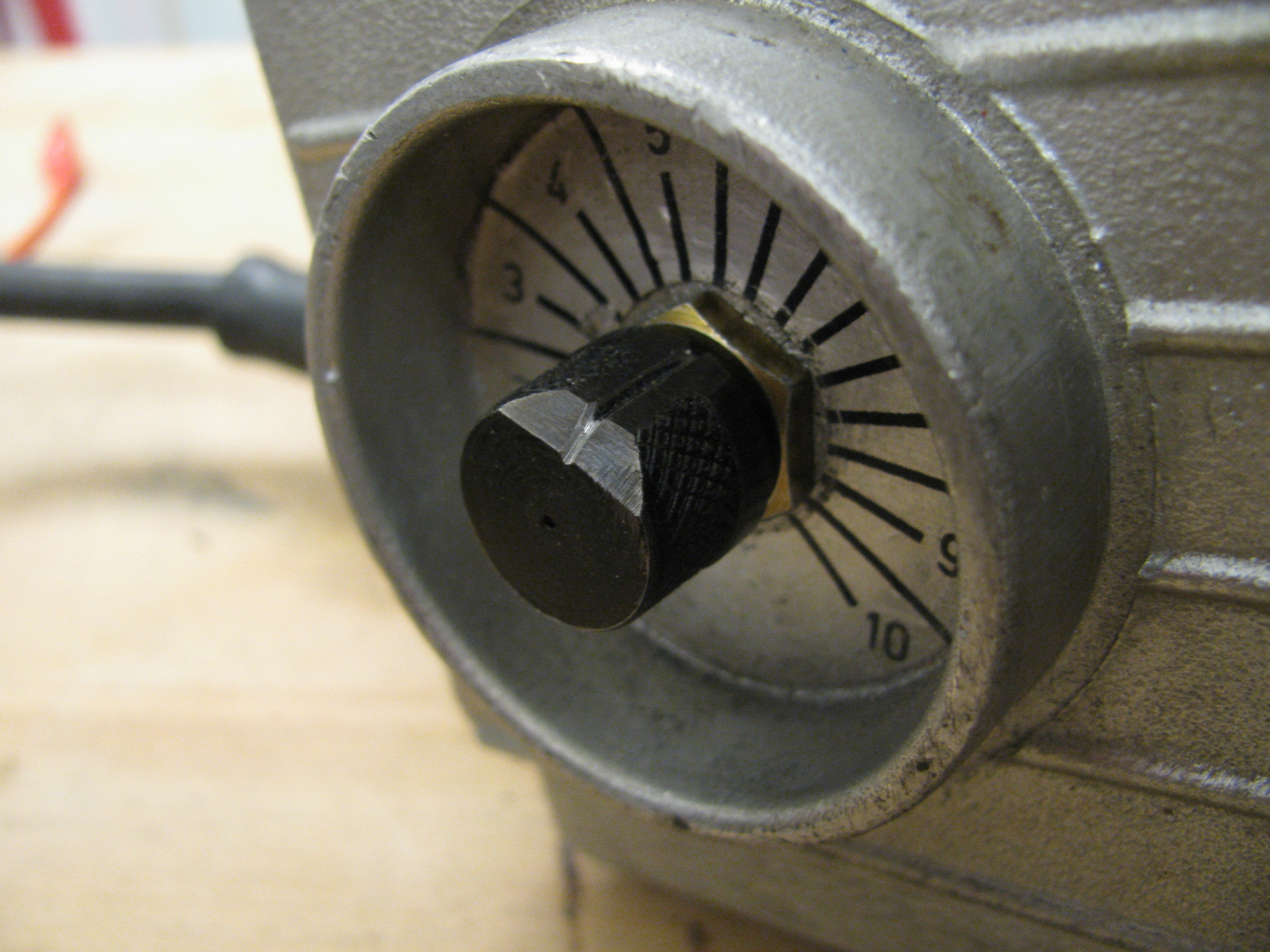
Et voila, DIY machined pot knob (browned steel) with allen screw (not visible):
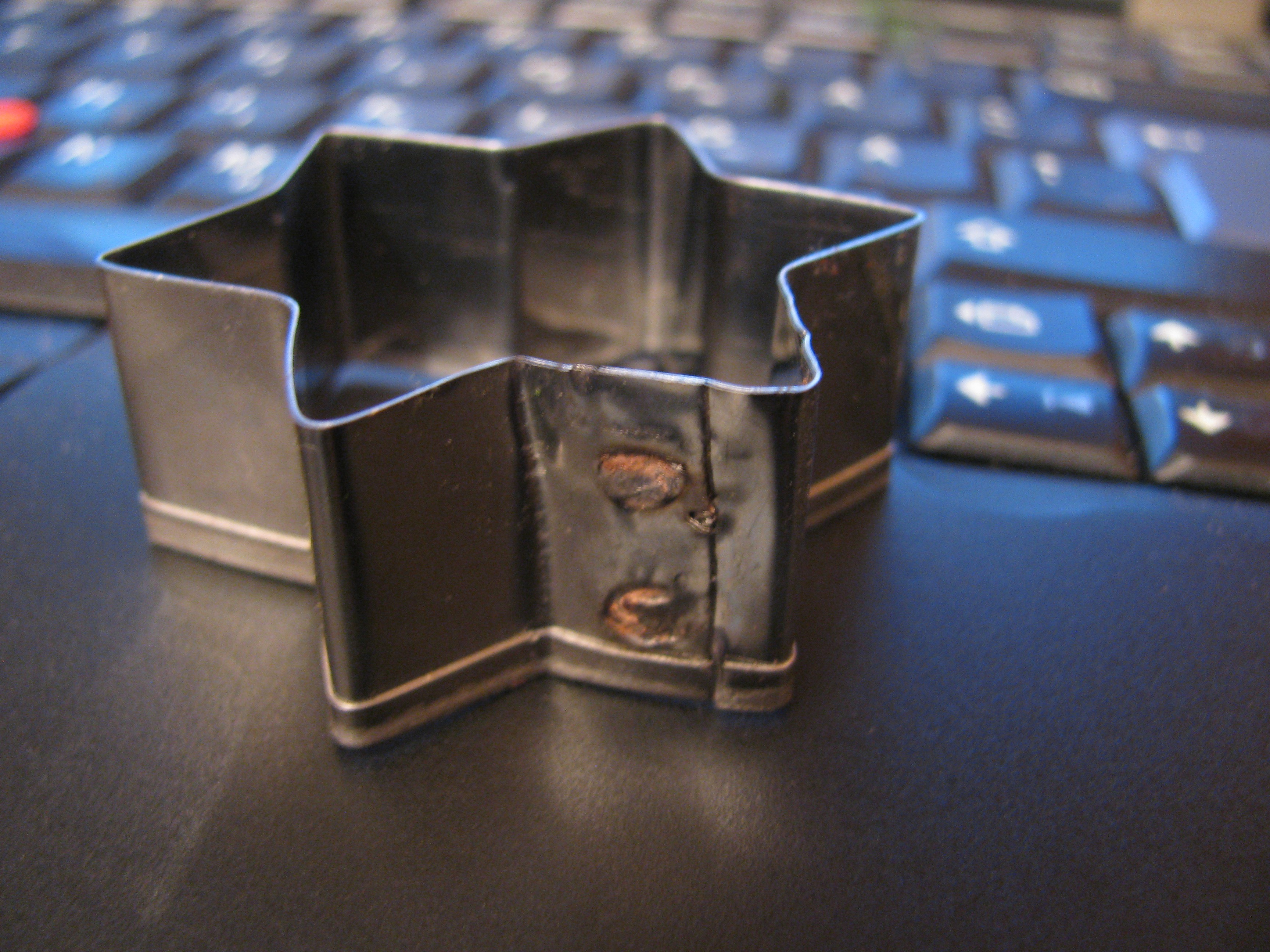
Yay, works again, time to make some cookies:
Ideas for future improvement
Door-stopper rubber feet.
Depending on the needed output power I may rewire the supply connector to run the device off 230V instead of 400V. This reduces the output power, but I don't want to use the device on thick sheets (it completely melts away two 1mm sheets if set too long) if the control circuit and relay allow. The control circuit transformer allows 220V operation (additional tap), but I try to avoid re-opening this device without a good reason.
As the device holds two 10mm diameter copper cylinders as electrodes, it is easy to get new electrodes (cheapest way is a 2 m long cylinder) and prepare them on the lathe for various tip sizes. It is possible to build an adapter to weld together battery packs...
 Yann Guidon / YGDES
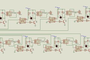
 UTSOURCE
 Boelens, Leland
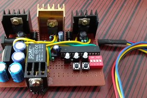
 Akash Kollipara
I have just purchased this exact spot welder. I can't tell you how much help this has been to me! Thank you so much for documenting the repair :-)
I too wonder about the switches - did you ever find an explanation or description of their use?