 dhgoldberg
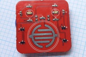
Here's a quick clip of one of the modes. I'll get the PCB for the brains of the system soon and I'll try to throw together something a little better.
0%
0%
Become a Hackaday.io member
Already have an account? Log in.
Just one more thing
To make the experience fit your profile, pick a username and tell us what interests you.
Pick an awesome username
hackaday.io/
Your profile's URL: hackaday.io/username. Max 25 alphanumeric characters.
Pick a few interests
Projects that share your interests
People that share your interests
 Mahesh Venkitachalam
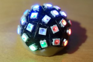
 Erik Bosman
 C. Scott Ananian
 Chris Miller