 jacksonliam
Here's the money shot!
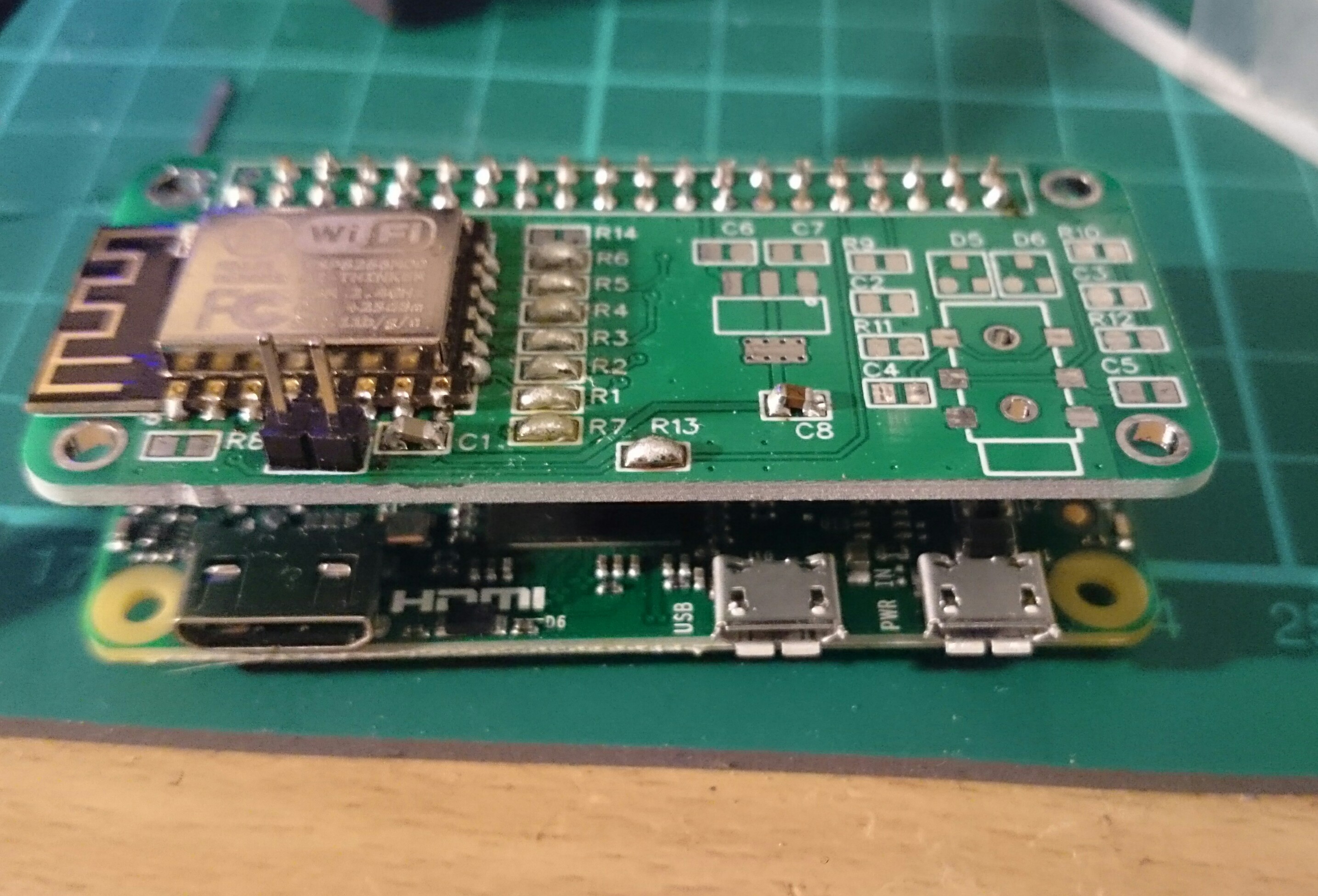
Ignore the poor 0603 soldering, I've only done QFP smd before!
Didn't bother with the resistors just did solder bridges. Getting 28Mbit/s pulling a file from my server.
I got the header placement wrong, so the Pi and board are offset by about 1mm, I'll fix it in easyeda but am not bothered enough to order more boards!
Next I'll try putting the flash to sleep with 4 bit SDIO.
I want to try the audio but the pack of smd resistors I bought doesn't have any value below 600 ohm for some reason!
Discussions
Become a Hackaday.io Member
Create an account to leave a comment. Already have an account? Log In.
Well done! Looks really good for a first pass, and of course it works which is the big achievement for the first spin of any board. I've never seen EasyCAD or their service and
Have you tried it at a 62.5MHz SDIO clock? I'm curious if it's just me or if there's something about the ESP-12 module that keeps it from working.
I'm very interested to hear how the 4-bit + flash sleep mode stuff works out.
SMD is a challenge, and IMO QFP is harder than discretes or even QFN. Looking at the solder, I think you'd have a much easier time if you flux all the pads first. The flux pens with plain 'ol rosin are great for this, or you can make your own: https://hackaday.com/2012/09/19/diy-flux-comes-straight-from-the-tree/ . The flux in flux core solder usually isn't enough. It shouldn't affect operation if you leave the residue behind. But if it bothers you, soak it in isopropyl and use a short bristle brush to loosen the goop.
If I could make some suggestions for rev 2, and I'm being REALLY nitpicky here:-Put vias through to the other layer on each of the pads on the audio jack. SMD jacks are notorious for being easily ripped off the PCB, and a few vias will stake the part more solidly in the board. You can prevent the via from sucking away too much solder if you make sure it's covered in mask on the other side (more noticeable/problematic if you do stencil & reflow).
-Another on the audio jack: make the alignment pegs non-plate through holes (NPTH) or they'll get melty if you reflow the board. Also NPTH holes are rougher and will bond better with glue if you choose to squeeze some epoxy down those holes.
-The ESP-12 shouldn't be flush with the edge of the board. Regardless of how clear you keep the underside and space around the antenna, the Pi will block a good swath of the radiation pattern. "But Andrew, didn't you do that on your last board?" Yes. Yes I did. And I'm fixing that in the next rev by hanging the antenna part off the edge.
Are you sure? yes | no
Thanks for the tips! I do have a flux pen, I perhaps went a little light, I think my main problem is crappy old lead free solder!
I want to make the Pi mount holes non plated/masked like on the Pi in the next rev, the audio jack ones are just part of the footprint I used (I didn't make any of the footprints) easyeda has a big built in library). But perhaps I can edit it :-\ very good point about mechanical vias, I'll definitely add those!
I did think about letting the antenna hang off, but I actually want the board to be no bigger than the Pi zero for my projects. I could make the board have a cut out around the antenna if that's likely to help? But it would still have the Pi below it, so I guess not much?
I did find the headers much more difficult to get good solder joints on than usual, I think too much copper to heatsink, especially on the GND pins. I set the iron to 380C which should've been plenty hot enough! Might be crappy solder problem again though.
Are you sure? yes | no
Lead free isn't too bad if you crank up the heat and use more flux. If you're having trouble with through hole and ground plane connected pads consider using a fine chisel tip if you're using a conical. Since you've got a temp controlled iron, cranking up the heat isn't going to make as much difference as making sure you've got good thermal transfer between the tip and work.
I think the gap between the Pi and the board from the HAT header should be sufficient for antenna clearance. My "Pants" are meant to be much closer to the back of the Zero so extending the module makes more sense. You should experiment with both nylon and metal standoffs to see if the metal affects the range.
Are you sure? yes | no