 W4KRL
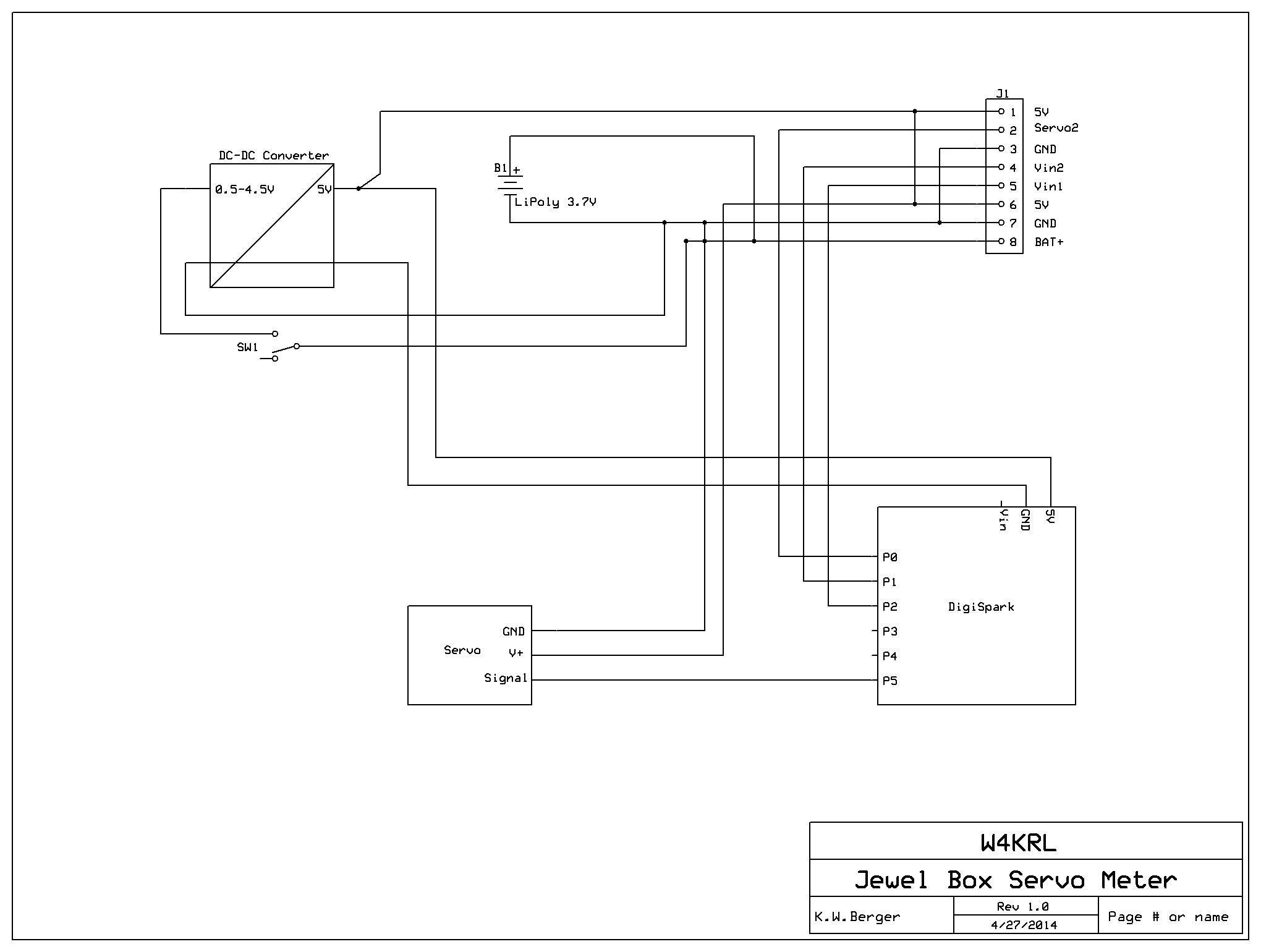
W4KRLSchematic

Build a meter in a jewel box using a micro-servo driven by a DigiSpark.
Already have an account? Log in.
To make the experience fit your profile, pick a username and tell us what interests you.
Schematic

Good accuracy and linearity.
// DS_ServoMeter
// Karl Berger W4KRL
// April 27, 2014
// Released into the public domain
// Converts a 0 to 5 Volt signal into a corresponding
// position on a servo. The servo command is smoothed to
// reduce jitter.
// Uses SimpleServo in the DigiSpark library by
// Benjamin Holt
#include <SimpleServo.h>
//create a servo object
SimpleServo myservo;
// The analog input signal is connected to P2
// For pin mapping see:
// http://digistump.com/wiki/digispark/tutorials/pinguide
const int kAnalogInputPin = 1;
// connect the servo signal line to P5
const int kServoPin = 5;
// Most servos are rated for 180 degree span but may be non-linear near
// the extremes. A meter span of 120 degrees or less is more reliable.
const int kScaleSpan = 120;
// 4 samples provides good smoothing. More will slow the response.
// Less will increase jitter.
const int kSmoothingSamples = 4;
//int smoothed_val = 0;
// attach the servo to a pin then exercise it
void setup(){
myservo.attach(kServoPin);
ExerciseServos();
}
// read the analog signal, smooth it and convert it to a position
// in degrees for display by the servo
void loop(){
// static variables retain their value between function calls
static int smoothed_val = 0;
// read the input voltage
int val = analogRead(kAnalogInputPin); // this is pin P2
// smooth the value by keeping a moving average
smoothed_val = smoothed_val + ((val - smoothed_val) / kSmoothingSamples);
// rescale val to the meter span
val = map(smoothed_val, 0, 1023, 0, kScaleSpan);
//command the servo to the corresponding position
SetServo(val);
//add some delay to let the servo seek its position
delay(15);
}
//adjust the motion of the servo to match the actual
//position to the command
void SetServo(int val)
{
const int kServoZero = 20;
const int kServoFullScale = 150;
int pos = map(val, 0, kScaleSpan, kServoZero, kServoFullScale);
myservo.write(pos);
}
//Position at zero and full scale to check calibration
void ExerciseServos(){
const int kDwell = 1000;
SetServo(0);
delay(kDwell);
SetServo(kScaleSpan);
delay(kDwell);
SetServo(0);
delay(kDwell);
}
Added some detail to the construction and adjustment steps.
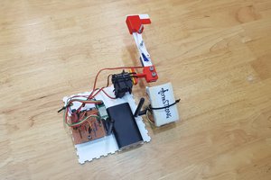
Find a small wooden box with a lid that has a transparent panel in the lid. My box had a thin wooden panel so I had to carefully cut out one end to remove the panel. Remove all the hardware. Stain and finish the box. Cut a piece of plastic from a CD box to replace the wood panel. Reassemble.
Program the Digispark and temporarily connect the servo to test the software and servo. I had a batch of 5 identical servos. Two of them rotated contuously when the Digispark was reset. The other three worked fine. One of those three was very jittery. I thought they were cheap but buying five to get two working is not a bargain.
Test fit all the components in the box to find the best arrangement. Cut a piece of strip board 8 rows wide and up to about 25mm long that will fit flat on the floor of the box. The strip board will act as a bus to connect to the header. I placed the trace side up so I could solder directly to the traces. You may be able to prewire the board in a more conventional manner but then you would have a challenge soldering it to the header.
 Juin Lee
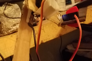
 Arnov Sharma