Jayraj Desai
I was reading some article where, writer was trying to impress upon the affect of Reaction time on life of athletes, snipers, cricketers and baseball players. Finally he concluded with its effect on life of normal people and I was amazed to see that reaction time had many implications on our day to day life.
For example a slower than normal reaction time while driving can have grave results.
I thought, How can I measure my reaction time?
Following is the result.
Step 1: Things we will need
Following is the list of things we will need to measure our reaction time.
Hardware:
- 3 push buttons
- 2 LEDs (color of your preference)
- 10K Ohm (3 in number) and 100 Ohm (2 in number)
- few connecting wires
- Bread board
- Arduino uno or Arduino duemilanove
- USB A to B cable
Software:
- Arduino IDE
Above mentioned components must be lying on floor of an electronic hobbyist :).
Step 2: What will be our procedure to measure reaction time(RT)?
There are many reaction time involved with our human body. we have Audio RT , visual RT, Touch RT and many more. In this instructable we will look at measuring
Visual Reaction time.
Procedure of measuring Visual Reaction Time:
- Pop a message on serial monitor of Arduino "press ready button when you are ready"
- When person under test presses ready button, after some random time interval , one of the two LEDs must lit-up that too randomly.
- Person under test should press the corresponding button as soon as possible.
- Arduino will take the note of time difference between LED lighting up and person pressing the corresponding button.
- Put the message of the measured reaction time on Arduino serial monitor.
Let me clarify that from the list of hardware components that i have mentioned, out of 3 buttons, one button will act as ready button and remaining two buttons will correspond to two LEDs i.e. LED1-->BUTTON1 , LED2-->BUTTON2. which means if LED1 lights up person under test should press BUTTON1 similar is the case for LED2.
Step 3: Putting things together
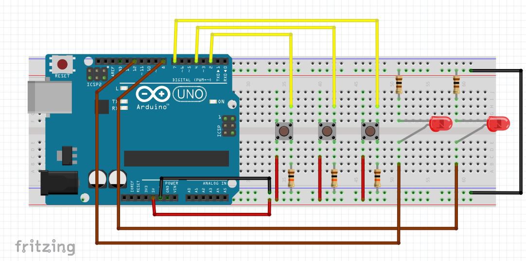
In the image above you can see the construction of the circuit. let me put up few points here.
- connect 5V and GND from arduino board to your breadboard.
- connect cathode of both LEDs through current limiting 100 Ohm resistors.
- connect anode of LED1 and LED2 to pin number 8 and 12 respectively.
- plugin push buttons as shown in the image. (in case of push buttons when button is open leads on sides are shorted, when button gets pressed diagonal leads
- gets shorted)
- connect 10K Ohm resistor as shown in the image, this acts as a pull down resistor.
- connect other lead to 5V rail on breadboard.
- and finally connect buttons to pin number 2, 4 and 7 of Arduino board.
Please Note: Pin numbers that I have mentioned above can vary as per your choice, I have just mentioned my preference.
If you have doubt in any of the above steps, just go through attached video.
Step 4: Lets Code
I have attached Arduino code for the instructable, that you can download and start playing but I suggest you write your own. Following are few points that you need to keep in mind while writing your code.
- Take care of Denouncing of push buttons.
- Take care that code should provide good resolution in measuring reaction time.
- Use serial monitor for debugging as well as human interface.
If you have doubt in any of the above steps, just go through attached video.
// set pin numbers:
const int buttonPin1 = 4;     // the number of the pushbutton1 pin
const int buttonPin2 = 2;     // the number of the pushbutton2 pin
const int buttonPin3 = 7;     // the number of the pushbutton3 pin
const int ledPin1 = 8;        // the number of the LED1 anode(+) pin
const int ledPin2 = 12;       // the number of the LED2 anode(+) pin

// Variables will change:
int ledState1 = LOW;         // the current state of the LED1
int ledState2 = LOW;         // the current state of the LED2
int buttonState1;             // the current reading from the input pin1
int buttonState2;             // the current reading from the input pin2
int buttonState3;             // the current reading from the input pin3
int lastButtonState1 = LOW;    // the previous reading from the...
Read more »

 Kirschner Christoph
 Enrique
 Setvir