 Peter Noyes
At this point, there is only one working Dodo in existence, so not quite extinct ;-), but this needs to change! The next step in getting more Dodos out there is a new hardware revision.
For a bit of history, the version 1.0 boards had several known problems, so it never seemed worth it to make any more prototypes. There was a version 1.1 that was designed to correct the most glaring issues, but no boards were ever fabricated because a more extensive update is really what was needed. Well, the time is now! Version 1.2 boards are off for fabrication.
Here are the highlights:
- RAM Upgrade. Now all 32KB is accessible
- In place firmware updates
- Faster game flashing
- Thinner, no longer uses IDC cables between boards
- Battery powered. Will run off of 2 AA Batteries.
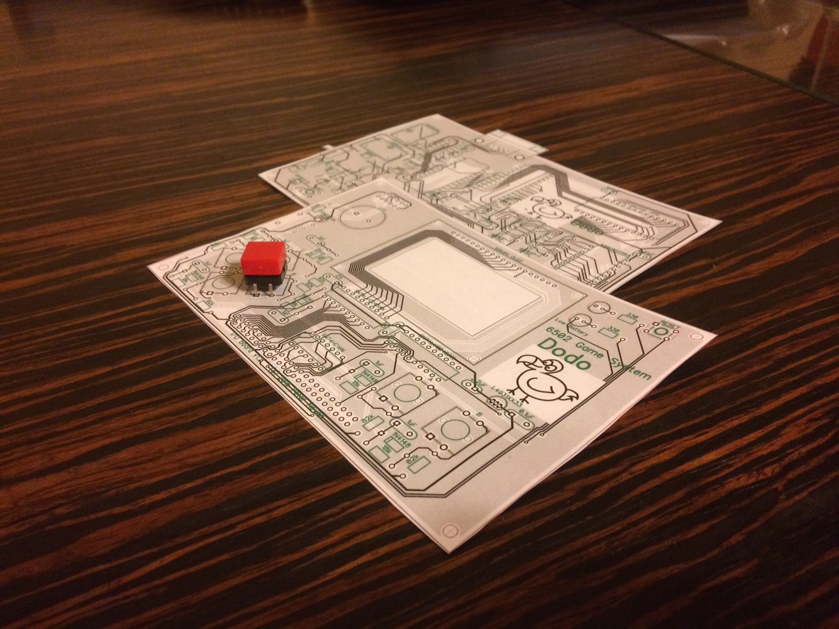
Above is a mockup of the new PCBs that I printed out. I have learned my lesson and will now always print these out and do some test placements of components.
The RAM upgrade opens up the possibility of adding a BASIC interpreter to Dodo. The plan is to allow 6502 Assembly, C, and BASIC as different options for game development, but all using the same API.
Dodo 1.0 supported flashing game cartridges over serial, but updating the firmware stored in the EEPROM required extracting the chip and using a dedicated programmer. The new Dodo will be able to program the EEPROM over the serial port.
The new Dodo will also have RS232 control lines connected which will enable more efficient communication that will ultimately result in faster game flashing.
Now the boards will be able to be mounted closer together, which means that the overall thickness of the device will be substantially less.
Finally the new Dodo is battery powered. Two AA batteries should last around 10 hours. There will even be a low battery indicator!
The battery circuit uses the Max756CPA+ which is able to boost the voltage of 2 AA batteries up to the 5V that Dodo needs. In the video above I am showing the test circuit I breadboarded to help fine tune the resistor values needed for the low battery indicator. The Max756 chip has an open drain low battery output pin that is driven low when a reference voltage falls below a 1.25v threshold. I wanted to show the low battery indicator when the voltage is 2v, so a voltage divider is needed to drop it down to around the threshold. In the video you see the second LED turn on as soon as the voltage falls to 2v, which is exactly what I want! The 2v is chosen based upon looking at the discharge curve of AA batteries and that is around the inflection point where the voltage really starts to tailspin.
Once I have the new boards in my hands and have assembled a few prototypes, the next step will be to make some software updates to take advantage of the new hardware features. At that point the project is basically complete. If there is interest I will make a kit available on Tindie.
Discussions
Become a Hackaday.io Member
Create an account to leave a comment. Already have an account? Log In.