Close
0%
0%

Solar Charge Controller MPPT Test Facility

A Banana Pi- based system designed to test the performance of solar charge controllers

Similar projects worth following
There are a lot of solar charge controllers, including those that claim to do maximum power point tracking. Liporider, Sparkfun, Adafruit, some on Ebay from Chinese companies, and Arduino-based projects. I m working on a system that allows to test the performance of these charge controllers, based on a Banana Pi with an I2C voltage and current sensor, variable load, and light source for indoor testing. I used my Zen Toolworks CNC to make a PCB as a "hat" (add-on board) for the Banana Pi. The software is based on a web server that runs on the Banana Pi and can save the data to a mySQL server so that the data are accessible from anywhere. I am thinking about having a randomized light source control to simulate cloud cover and to test the tracking capabilities of the charger. The overarching goal is to keep the cost low. This project came out of a solar-charged rover that I am also building.

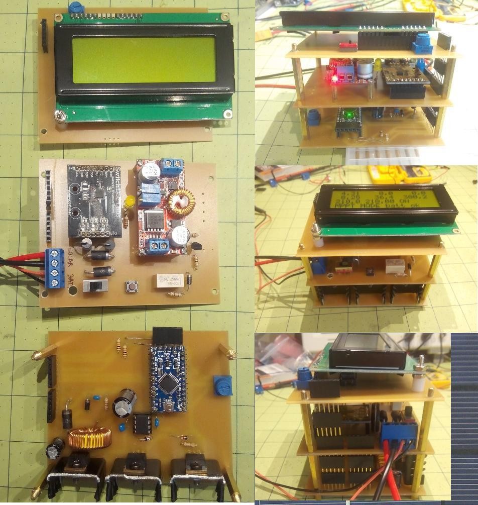
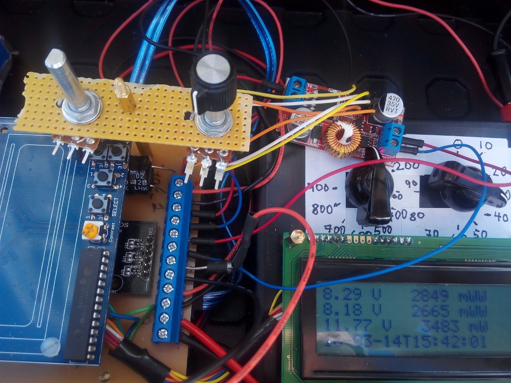
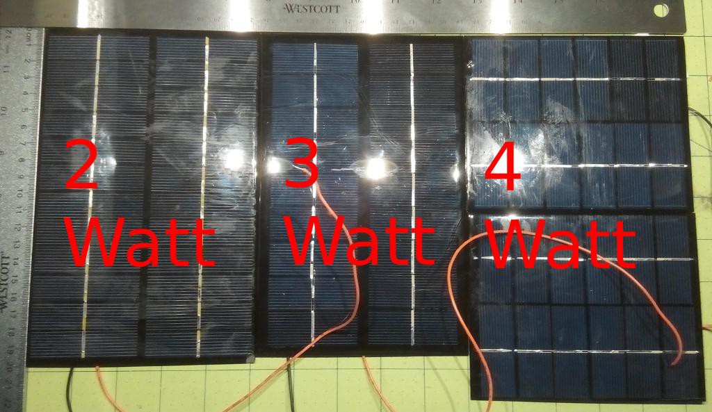
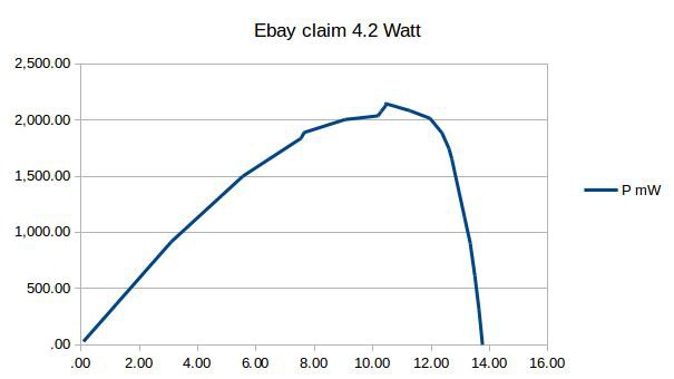
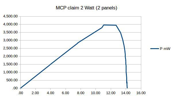
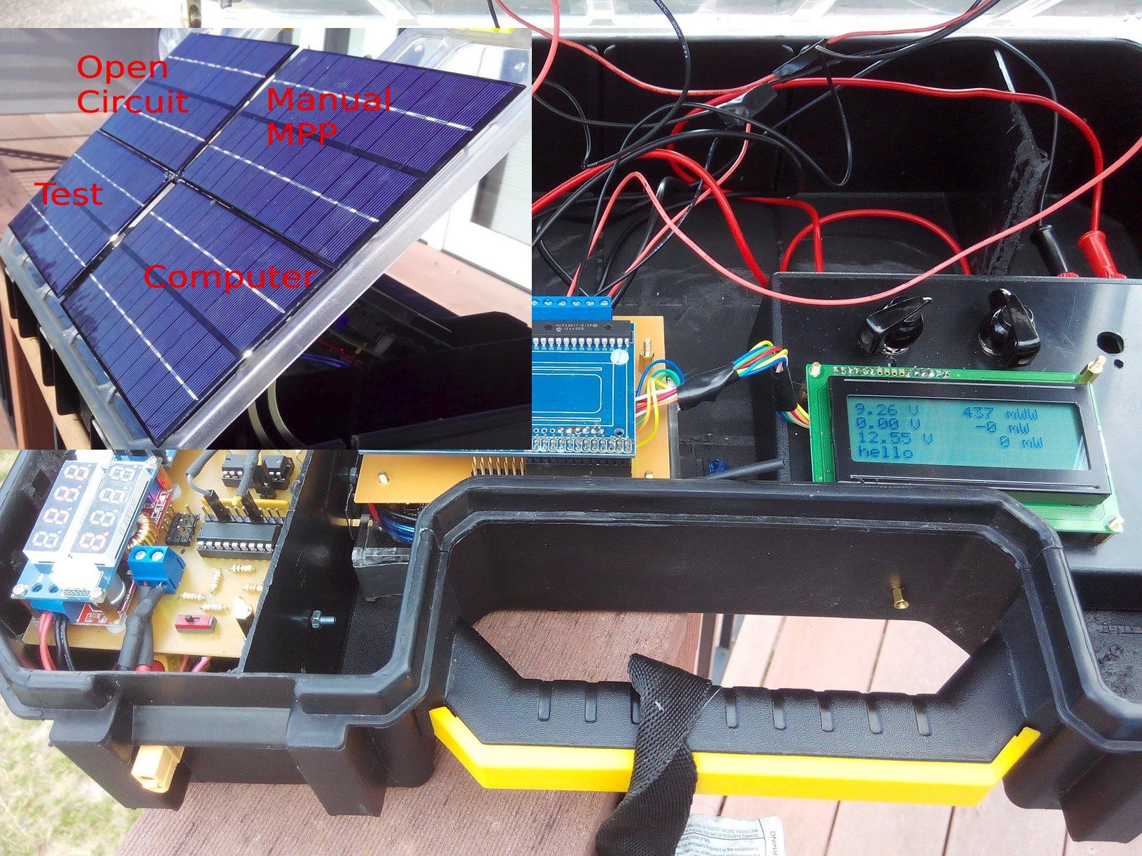
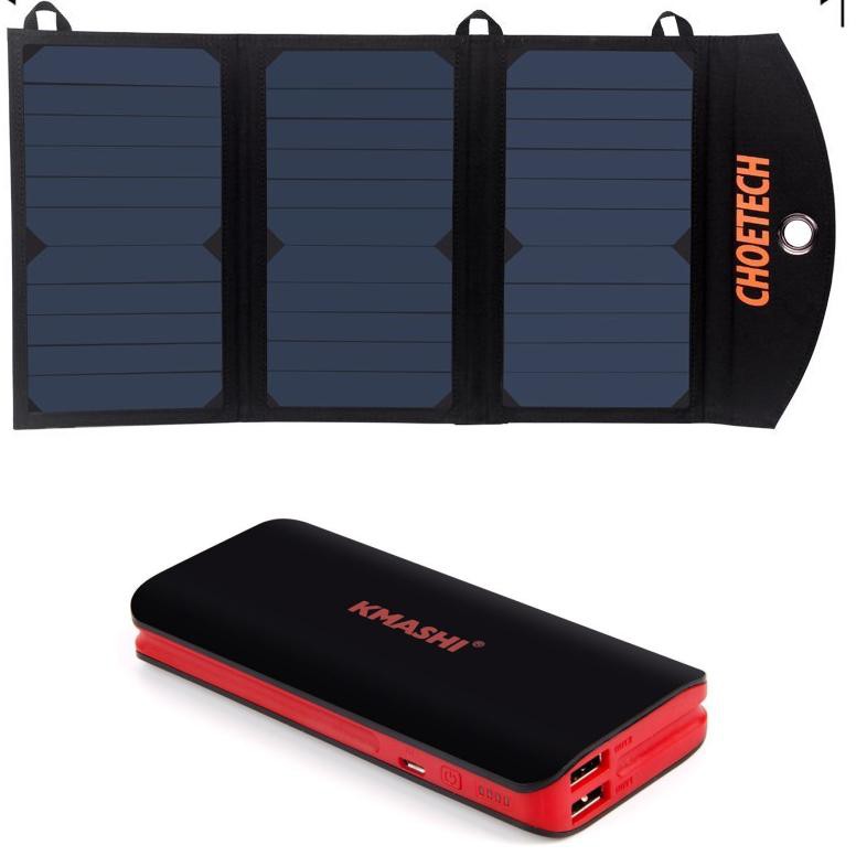
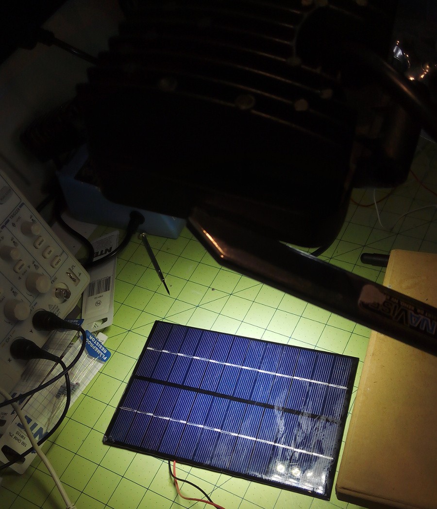
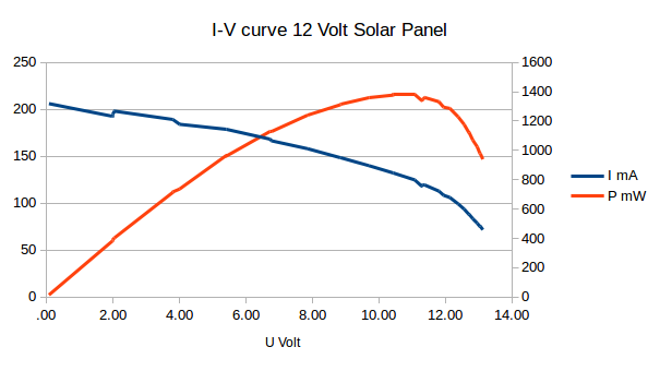
Here is the concept as I am currently thinking: Two identical solar panels are exposed to the same irradiation, and on both panels, the output power is measured. The first panel is a control, and it will be set to operate at the maximum power point (for the given conditions). This will result in the control outputting a certain power. If the second solar panel with the charge controller under consideration gives out the same power, it is operating at the maximum power point. If it doesn't, it is not MPPT!

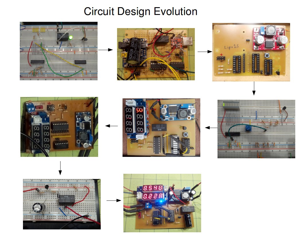
Of course, things are not that simple, and the real goal is to learn about solar charge controller design and to find the best design.

sch - 295.29 kB - 02/16/2016 at 02:53

Download

brd - 85.33 kB - 02/16/2016 at 02:53

Download

Portable Network Graphics (PNG) - 73.21 kB - 02/01/2016 at 23:56

Preview
Download

INA3221_hat.sch

Eagle file

- 129.54 kB - 02/01/2016 at 23:57

Download

INA3221_hat.brd

Eagle file

- 68.18 kB - 02/01/2016 at 23:57

Download

View all 6 components

  • MPPT Solar Charge Controller works

    Tobias06/09/2016 at 21:27 0 comments

    I have been working on making an MPPT solar charge controller and it is now at the point where it works. Here is a link to the project:

    https://hackaday.io/project/10671-arduino-mppt-solar-charge-controller

  • MPPT Solar Charger from Buck Converter-Fail

    Tobias03/18/2016 at 01:27 4 comments

    I tried to build an MPPT solar charge controller by just using an inexpensive buck converter which you can get on Amazon for $10. The idea is to use the potentiometer on the buck converter that sets the maximum (constant) current to set the current to a value at which the solar panel operates at maximum power. If this worked, I could use a digital potentiometer, connect it to an Arduino, and implement an algorithm in the Arduino that automatically sets the buck converter to the MPP of the solar panel.

    But that didn't work-here is what happened:

    I start out with a very low current limit setting which makes the solar panel operate at about 14 Volts an a very low wattage of about 0.1 Watts. Then I slowly turn the potentiometer to increase the current limit and hopefully stop at the maximum power point. But what happens is that the voltage suddenly flips to the battery voltage, and the harvested power is far below of what the solar panel can deliver. At that point, the battery is at 8.18 Volts, and it forces the circuit to run the solar panel at 8.29 Volts which results in a power of 2.8 Watts at the solar panel. However, the solar panel is capable of producing 3.5 Watts under the given conditions which corresponds to a solar panel voltage of 11.77 Volts and which I verified with the variable load resistors.

    So the voltage flips between about 14 Volts (open circuit voltage) and the battery voltage, and no matter how carefully I turn the potentiometer, I just cannot get it to stop in the middle at 11.8 Volts, the MPP voltage.

    I'm not sure if this behavior is the result of the used controller chip on the buck converter, but at this point, I am planning to build a system where I have more direct control over the duty cycle of the PWM.

  • Solar Simulator Problem and Solution

    Tobias03/13/2016 at 00:18 0 comments

    I got a Mars Hydro grow light as recommended by mjlorton for indoor PV testing, and it works great, just one problem: I get a huge AC component on top of the DC voltage coming out of the solar panel, sometimes as large as 50%. This is not good for recording power data and also not what the actual sun does. This problem was easily solved by adding a large capacitor in parallel to the solar panel output (At least 1000 mikroFarad).

  • Solar Panel Testing

    Tobias03/02/2016 at 02:21 0 comments

    vendor note url voltage current mA width in length in width mm length mm area (cm^2) watt claim watt measured watt/area(m^2)
    MCP
    link 6.00 330

    136.00 110.00 149.60 2.00 2.00 133.69
    Sunnytech B043 green letters link 9.00 333

    195.00 125.00 243.75 3.00 2.80 114.87
    ebay
    link 12.00


    200.00 123.00 246.00 4.20 2.20 89.43

    Tests made at maximum sun light, 1312 Watt/m^2 measured with Drmeter instrument


  • First Prototype

    Tobias02/25/2016 at 02:11 0 comments

    Here is a picture of the first prototype. It consists of a modified toolbox with the electronics inside of it and a hinge support that lets us tilt the solar panels towards the sun. The lid has four identical solar panels on it. One is operated as an open circuit, and its voltage is measured. The maximum power point of a solar panel is approximately at 75% of the O.C. We can compare this voltage with the voltage that the charge controller sets itself to. A second panel is connected to the resistor decade box where we can manually search for the MPP. This is the second reference. The third panel is connected to the solar charge controller that we are testing. The fourth panel powers the microcontroller. The microcontroller has wifi and runs a LAMP server. The measurement data are logged in a mySQL database that can be accessed through a web page.

  • Solar Power Controller Evolution and Lessons Learned

    Tobias02/16/2016 at 02:40 0 comments

    I started out with the goal of powering a single computer board with a solar panel and a battery backup.

    The simplest solution appeared to be: A USB charging solar panel with USB power bank

    This did not work because some USB power banks do not output power when a charging cable is plugged in. In addition, I noticed that the Banana Pro will stop running when the battery voltage drops too low, but it will not reboot when solar charging increases the voltage because the voltage never went to zero. There is a region of voltage in which the microcontroller could be stuck for a long time, without actually running. So I came up with the idea of a circuit that has multiple comparators and a latch for hysteresis so that a controlled computer shutdown/ reboot can be accomplished. Here is the first breadboard implementation:

    and the first protoboard implementation:

    On the left is a Adafruit solar charger controller and on the right is a step-up boost converter to convert the 3.7 Volt of the Lipo battery to 5 Volt. The shutdown and the bootup voltage can be selected by choosing any of the pins on the pin header next to the LM3914.

    Since I was now making PCB's regularly, I also put together my Zen Toolworks CNC for PCB milling.

    This worked for a while, but eventually the boost converter burnt out, and I noticed that during boot, over 1 Amp can be pulled from the board! At the time, I was also looking for a rover platform, and the one that I chose has motors that need at least 6 Volts to run. So I decided to switch to Lipo 2S batteries which can provide between 7.4 and 8.4 Volts. This turned out to be a good decision because now, the microcontroller-caused current never goes above 300mA. I am convinced that buck-down conversion is more efficient than boost-up conversion, at the least, lower currents cause fewer problems. I would never voluntarily run a 5 Volt microcontroller from a 3.7 Volt battery again.

    The circuit for the LED controller had to be changed so that its turn-on and turn-off point could be set between 7.4 Volts and 8.4 Volts.

    Since I was using a new voltage, I had to get a new charge controller. I looked for lipo2S solar charge controllers and only found two on Ebay, both of which I ordered and both of which do not work (at all). So I used a step-down converter from a 12 Volt solar panel to 8.4 Volt with current limitation. The one that I currently use has a voltage and current display which is very useful.

    On the left is the buck converter for the solar panel and on the right is the buck converter to the microcontroller.

    I also added a 10-LED bar display to show the battery voltage, but removed it in the next revision because it interferes with the outputs to the latch.

    One problem I had with this circuit is that when I connected a solar panel under low lighting conditions, the relay would turn on and off at a high frequency (rattling sound) and eventually, the circuit stopped working, probably because the transistor or the relay burned out.

    I decided to try a time delay circuit, based on a capacitor, and also finally added a flyback diode

    In addition, I put a 200 Ohm resistor between the voltage source and the relay and the current dropped from 40 mA to some single digit number that is not even showing on my power supply's decimals. You can literally hear the difference in the relay sound when you increase the resistance. One of the reasons I like the relay over a solid state relay or a MOSFET is the audible feedback, and when the relay is off, it is really off.

    I took the board out in the sun today and exposed it to low light conditions where it turned on and off periodically, but this time, the frequency was less than once per second which is not going to destroy the relay. This condition only occurs under low light and when no battery is connected, which is only during maintenance, but now, that can't destroy my board either.

    ref: Designing a Li-Ion Battery Gauge with the LM3914 - EEVblog #204

  • Improved Power Monitor Pi Hat

    Tobias02/02/2016 at 00:08 0 comments

    Changes:

    The INA board is soldered to the hat, no more loose wires

    Screw terminals instead of pin headers

    Wider traces for the power-relevant connections

    I made the board a bit larger so that the screw terminal screws can still be reached with a screw driver when another hat is stacked on top:

    Side note: My Zen Toolworks CNC has turned out so useful for prototyping, it is easier to make a PCB with it than to solder it on a protoboard. One step closer to the dream of thinking of something and pushing a button on a machine that makes it. Plus, it is so much fun to watch the machine mill:

  • High Watt LED for Solar Panel Testing

    Tobias01/31/2016 at 00:02 0 comments

    I found this 48 Watt LED for $16 on Amazon and tried it for indoor testing. I only got about 180 mW out of my solar panel, about a factor of ten too weak, but still, good enough for some hard-and software development. Meanwhile, I saw a youtube video by mjlorton at https://youtu.be/bIzeLG-pMkE where he points out the potential of growth lights for sun simulation. For example, there is a MarsHydro 300 Watt light for $99 http://amzn.com/B00XC3LBI2. These lights might be closer to the actual sun frequency spectrum, but I'll wait and see what his tests reveal.

  • I-V curve and Maximum Power Point

    Tobias01/27/2016 at 01:21 0 comments

    This curve was taken around noon with the panel laying flat. The maximum power point corresponds to a load of about 100 Ohms. Note the maximum power of 1.4 Watts, and even when the panel was oriented perpendicular to the sun, only 1.6 Watts were reached. The panel is advertised at 4.2 Watts - What? Could it be that the traces on the PCB are too thin? The Molex connectors too high resistance? Time to redesign the PCB, and to try XT-60 connectors or screw terminals?

  • Resistor Decade Box Load for Solar Panel Testing

    Tobias01/27/2016 at 00:57 0 comments

    This resistor decade box can be set to a resistance between 10 and 290 Ohm in 10 Ohm steps (up to 990 once I solder in the remaining resistors). Initial tests turned out that single-digit Ohm values were not useful for my solar panels. Here is how I determined the wattage: If the panel can give out 20 Volts max. and in the worst case, has no own resistance, what is the wattage coming through the resistors?

    Resistance voltage power W
    10 20 40.00
    20 20 20.00
    30 20 13.33
    40 20 10.00
    50 20 8.00
    60 20 6.67
    70 20 5.71
    80 20 5.00
    90 20 4.44
    100 20 4.00
    200 20 2.00
    300 20 1.33
    400 20 1.00
    500 20 .80
    600 20 .67
    700 20 .57
    800 20 .50
    900 20 .44

    On the first line, two 20 Ohm, 25 Watt resistors in parallel give 10 Ohms with maximum 50 Watt which is above the required 40 Watts, etc.

    Why resistors? a) cheap b) easy to understand c) no power supply required, good for outdoor testing.

View all 11 project logs

Enjoy this project?

Share

Discussions

Lukas Fässler wrote 08/01/2018 at 10:52 point

Hi Tobias

Thank you for sharing this interesting project. I'm working to complete my MPPT Solar Charger (it's on Hackaday, too) and this kind of testing facility might prove very useful when optimizing the MPPT part of the code...

Lukas

  Are you sure? yes | no

Similar Projects

Does this project spark your interest?

Become a member to follow this project and never miss any updates