 cyplesma
The real key to this platform will be the tool fixture adapter mounted to the tool fixture itself and the carriage mounted to the X axis gantry (left to right direction). It will have one connector for the control sensors and drivers. One AC and or DC power connector, which ever is needed. A pair of headers that will indicate to the controller what type of tool fixture is mounted on the platform. If I use a 232 connector, I have lots of these, I can just use one pin as the common (Pin 9) I have 8 other pins to identify up to 255 (zero would not count in this case) other tools, so maybe use some 4 pin molex connectors from the shack, that gives me up to 7 different tools. The control headers between the tool itself and the platform main controller will be used based on the tool itself, probably just use a pair of 10/16 pin headers. Maybe it will be beneficial to use specific pins for specific sensors and or controls. A drill and a plastic extruder will both have a sensor to detect rpms and will also need to control rpms.
0%
0%
Become a Hackaday.io member
Already have an account? Log in.
Just one more thing
To make the experience fit your profile, pick a username and tell us what interests you.
Pick an awesome username
hackaday.io/
Your profile's URL: hackaday.io/username. Max 25 alphanumeric characters.
Pick a few interests
Projects that share your interests
People that share your interests
 Myles Eftos
 Greg Duckworth
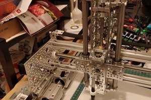
 Ted
Ted
 Alastair Young