 Christoph Tack
Test hardware
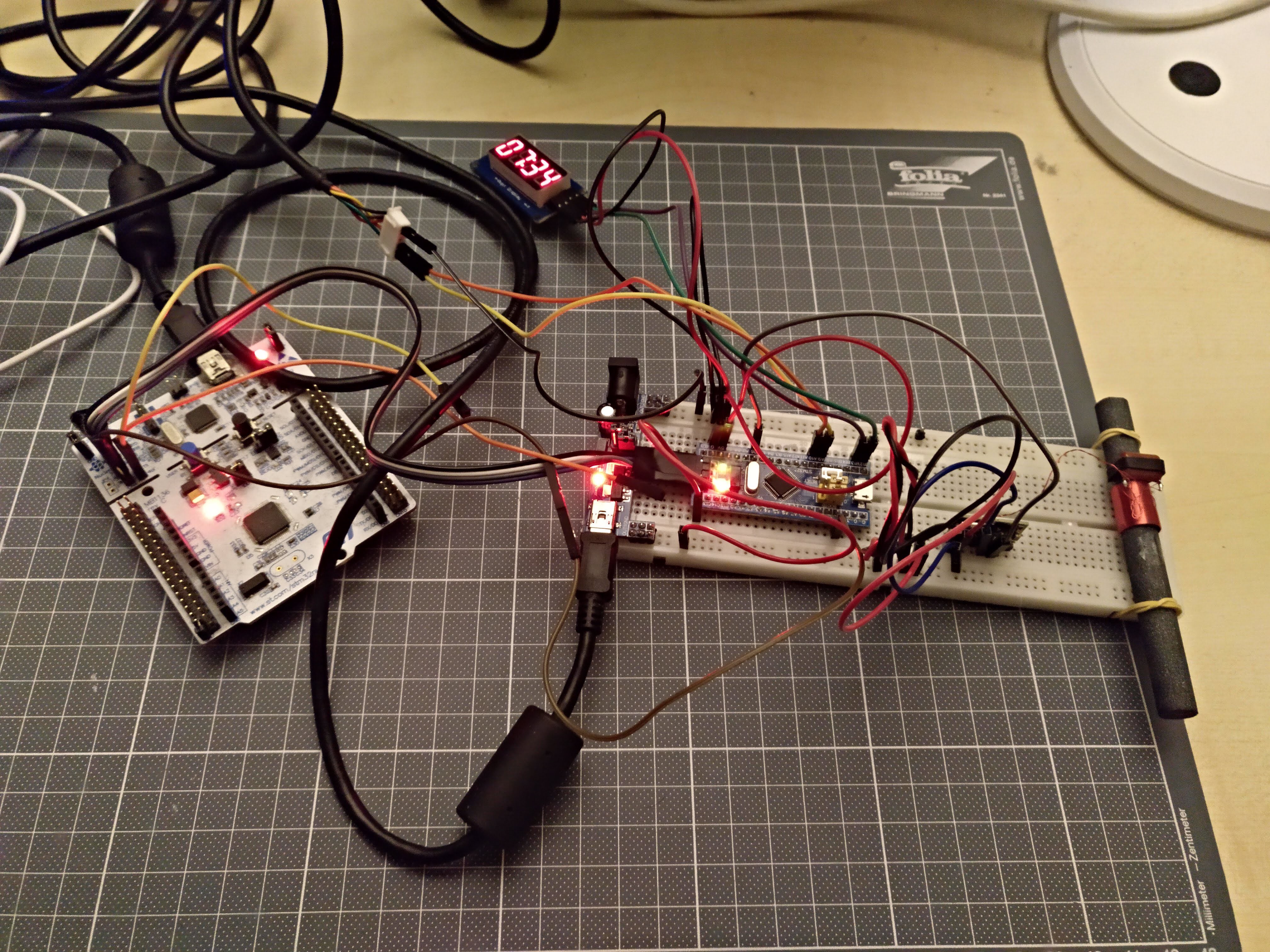
This setup has the BluePill on the breadboard, connected to a Nucleo debugger (white PCB on the left). The 7segment module on top connects to two GPIOs of the BluePill. The BluePill receives its DCF-pulse info from a DCF-receiver on the breadboard. That DCF-receiver is connected to a DCF-antenna, attached with rubber bands to the breadboard.
DCF-signals are very weak. Making breadboard connections with relatively long wires as done here, makes the BluePill a fairly good RF noise radiator. So with the setup as shown here, it's nearly impossible to get a correct DCF-reading. The picture was actually taken around 9PM. The DCF-library makes a best guess of the data it receives. There's no reliability threshold, so wrong data might be shown in the event of a useless signal. Most of the times, even with a bad signal, the clock recovers and finds the correct time.
I faced the same problems with the BluePill when trying to receive FM-RDS. Using a Nucleo, results were a little bit better, even with the same mess of wires.
Code can be found on Github.
DCF signal quality for the same setup the next day, on Sunday, about the same time of day was much better. No easy explanation about what caused such an interference on Saturday night.
Parameter setup
This design has quite a lot of parameters that can be set. It's challenging to find a way to set these all up easily using only a 32x16 display. The display can only show 10 characters at a time.
Menu input would be limited to using a rotary encoder or a few switches.
I have tried a few menu libraries for Arduino : Arduino Menu System, Arduino_LCD_Menu and ArduinoMenu. They all suffer from the same problems:
- Requiring a lot of key presses for setting up parameters
- Difficulty of displaying the menu hierarchy in a way that is simple to grasp. E.g. setting the weekdays for the alarms are four levels deep in the menu. Without a menu overview, it will be hard to keep track of what you're setting up.
Let's take the Google clock app for Android as a reference. This app allows to setup more or less the same parameters as listed below. Using the app, an alarm can be setup in less than 30s. This would be nearly impossible to do with a 32x16 LED array and four buttons.
Solution
Parameter setup will be done using physical switches. A combination of DIP switches and rotary switches will be used.
Advantages:
- Each parameter can be set without having to browse through the other parameters, speeding up the parameter setup process
- Parameter status is indicated by the physical state of the switch. This doesn't require power and doesn't cause undesirable light output at night.
- Depending on the target audience, the switch functionality can be implemented using DIP-switches and rotary switches or with panel mount toggle switches and rotary switches that allow for older people to control the device.
Disadvantages:
- Adds cost, because it requires a lot of extra hardware
- No other means for setup of parameters (e.g. through bluetooth) because the switches would no longer reflect the current settings. A way to circumvent this, would be to replace the rotary switches by rotary encoders & 7segment displays and replacing the dip switches by momentary switches and LEDs.
The input panel will be implemented on a separate PCB, allow for upgrade, changes in a future stage.
Menu structure
- Alarm 1 (Alarm 2 has the same menu structure). The menu item is dynamic. An icon shows if the alarm is enabled or not, followed by the alarm time
- Activation
- On
- Off
- Time
- HH:mm
- minutes can only be set in 5min. steps. It allows to set up time faster. Nobody wants to get up at three minutes past seven anyway.
- HH:mm
- Repeat
- Once
- Weekly
- M, T, W, T, F, S, S
- Daily
- Type
- SND + LIGHT
- SOUND ONLY
- LIGHT ONLY
- Sound (only when sound is enabled)
- Bamboo
- Jazz
- Guitar
- Piano
- Volume (only when sound is enabled)
- 0 to 100>#/li###
- Light (only when light is enabled)
- 0 to 100>#/li###
- Activation
Navigation
The Nokia 3310 features an elegant way of navigating the menu. Three buttons are involved:
- A two-way switch for scrolling through the menu.
- A "select" button to accept a certain choice
- A "back" button to cancel.
Time keeping
STM32 RTC
The STM32F103 on the BluePill has a built-in RTC. Luckily, there's already a library for it, so it should be a breeze to implement it. Or not...
Using code as is
To check the accuracy of the RTC, I wrote an application that can receive UTC epoch time from the serial port. The application also reports the difference with a newly sent UTC epoch time. Sending UTC time to the BluePill as follows:
echo -ne $(date +%s) > /dev/ttyACM0
Serial output from the BluePill:
PC epoch - RTC epoch = -553
Number of seconds RTC is running: 1910
PC epoch should be equal to RTC epoch, which it clearly isn't.
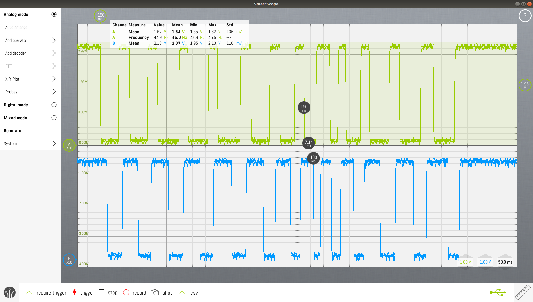
Checking up on the 32K crystal with an oscilloscope showed me that it isn't running. I measure 50Hz. Another BluePill from a different batch has the same problem.
Either the crystal is not properly setup in software, or it's a hardware malfunction.
By default, the example code of the library doesn't use the external 32K crystal (LSE), but the internal low frequency oscillator (LSI).
The LSE must be used as RTC clock source.
The code was first run on a Nucleo64 F103. The RTC should work properly on that official hardware:
PC epoch - RTC epoch = 0 Number of seconds RTC is running: 607
Running the code on a BluePill made me happy:
PC epoch - RTC epoch = 0
Number of seconds RTC is running: 30838
Beware of Chinese quality!
On another Blue Pill, when running the same code, the RTC lags about 8s/min. It's useless.
Time keeping in software
MCU keeps track of UTC, not local time
The MCU will keep time in UTC, not in local time. Yes, it involves a conversion each time the current time is shown to the user, but it least it's unambiguous. In western Europe, daylight savings time is still used. This means that at the last Sunday of October 3AM, we turn the clock back for one hour.
Suppose only local time is used and an event happens at 2.30AM that last Sunday morning of October, it can't be determined unambiguously when it happened. Was it at 2.30AM Summer Time or 2.30AM Winter Time? You can't tell because that day counts 25 hours and 2.30AM occurs twice.
Jack Christensen's TimeZone library converts UTC to local time.
Calendar events
The alarms in the clock are treated as events in a calendar. It's possible to set up three types of events according to the frequency of occurrence : once only, weekly or daily. Pat Deegan's Chronos library offers functionality for that.
The calendar is only some kind of database that pins events to time. The calendar has no knowledge of the current time.
The calendar can return the soonest event that will occur after a given time stamp. The time of this calendar event is then programmed into the RTC. As such, the application could go to sleep and only wake up when the time of the event is reached.
Alarm IO panel
LED control
The MCP23017 is used for charlieplexing 15 LEDs. Using the Chaplex library and replacing pinMode and digitalWrite functions by their MCP23017 counterparts is simply too slow. The LEDs are visibly flashing.
The solution was to adapt the Adafruit MCP23017 library and the Chaplex library. The MCP23017 library now opens up some internal functionality, such as setting pin direction for eight pins at once. The Chaplex library now prepares two registers for the the MCP23017 : pin direction and pin value. When these are ready, they can be sent over the (slow) I²C bus to the MCP23017. This dramatically reduces the number of I²C bus operations. There's no longer visible LED flashing.
Switch reading
The reading of the switches is done using the common matrix technique. Each "row" is sequentially pulled low while pullups are connected to the "columns". The delay caused by the I²C commands is beneficial here, as it removes the need for switch debouncing measures.
Rotary encoder reading
A common technique to read rotary encoders uses pin change interrupts. When a falling edge occurs in the green signal in the picture, then the level of the blue signal is read. If the blue signal is low, then rotation is clockwise. If the blue signal is high at the falling edge of the green signal, then rotation is counterclockwise (or vice versa). When directly connected to an MCU, implementing this is quite straightforward. In this design, the MCP23017 creates a delay, which might be a challenge. The blue signal only keeps its state for about 7ms after the falling edge.
After some time debugging my code for MCP23017 interrupts, I found out that the MCP23017 only supports three interrupt types : pin change, pin high and pin low. There's no support for making distinction between falling edge and rising edge pin interrupts.
If you configure the MCP23017 for interrupt on pin high (DEVALx=0, INTCONx=1, GPINTENx=1), the MCP23017 will generate interrupts as long as the pin is high. This is a level triggered interrupt, not an edge triggered interrupt. The datasheet is quite misleading in this regard.
The firmware uses MCP23017 pin change interrupts. Interrupts are generated on falling and rising edges on one of the two switch contacts. The STM32 is setup to generate interrupts at the falling edges of the IRQ line from the MCP23017. The interrupt routine on the STM32 reads the state of the two rotary encoder contacts. Rotating clockwise yields: 00,11,00,11,... Rotating counterclockwise yields 01,10,01,10,...
Menu rendering
This describes how the internal parameters of the clock will be shown to the user using the three output devices on the clock io panel : LED matrix panel, seven segment display and LEDs inside the switches.
Field
Fields are display elements that can show a value. The value can be changed in predefined steps between lower and upper limits. For the LED matrix panel, a bar graph drawing element is used. For implementation on the seven segment display, two fields, each consisting of two digits can be shown.
Select
"Select" is a display element that allows to select one out of many. It's only implemented on the LED matrix panel. A moving dot corresponds to the currently selected item
Toggle
"Toggle" is a display element that shows the status of a boolean. Only two states here: on or off. This is implemented for the switches alongside the edges of the clock io panel.
Discussions
Become a Hackaday.io Member
Create an account to leave a comment. Already have an account? Log In.