-
Menu mock-up
04/04/2016 at 21:27 • 0 commentsHi folks!
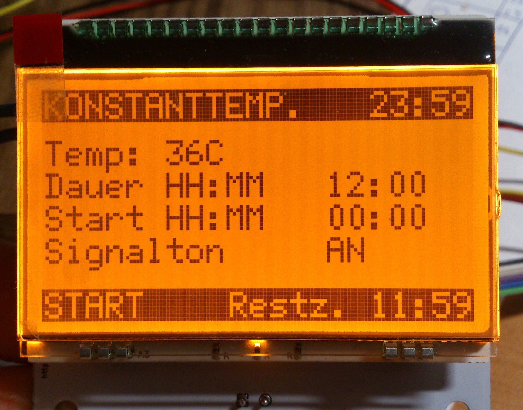
Progress is a bit slow at the moment, but I sat down and made a little mock-up of the menu. In the upper status bar there's the active mode and time. The bar at the bottom will have a start/pause button and the remaining time.
I did not yet decide what information I want to put on the main screen, there are things like temperature, start time and duration. Things will change for sure...
![]()
There will be a settings screen of course, I want to move global settings there. The screen above is where you enter all your parameters. It will be similar for all programs. Once started, it will change to some kind of status display, showing temperatures, time and some status icons.
Cheers!
-
PCB up and running
03/21/2016 at 20:48 • 0 commentsJust a quick update:
![]()
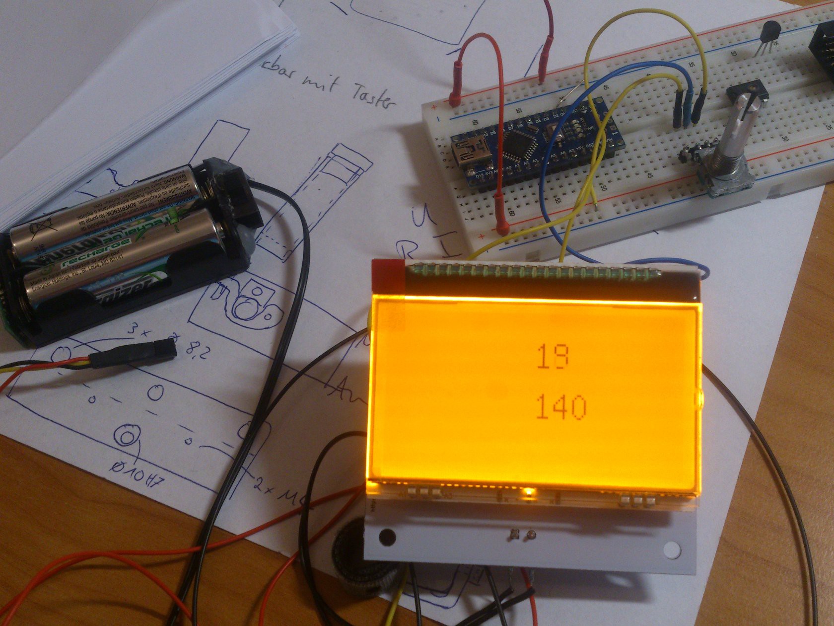
Board is up and running. It's just showing temperature and LCD background brightness level (0-255) atm which can be controlled with an encoder. I hope I'll have some spare time for my project over the following long easter weekend...
-
PCBs arrived – prototype assembled
03/16/2016 at 11:14 • 4 commentsYeeeeeeha! I got my PCBs 3 weeks after ordering (China to Germany)!
Soldering was a bit of a hassle and I managed to solder the Atmega the wrong way... DOH! So, fast forward to desoldering most of the parts (as I could get the damn thing off the board)...
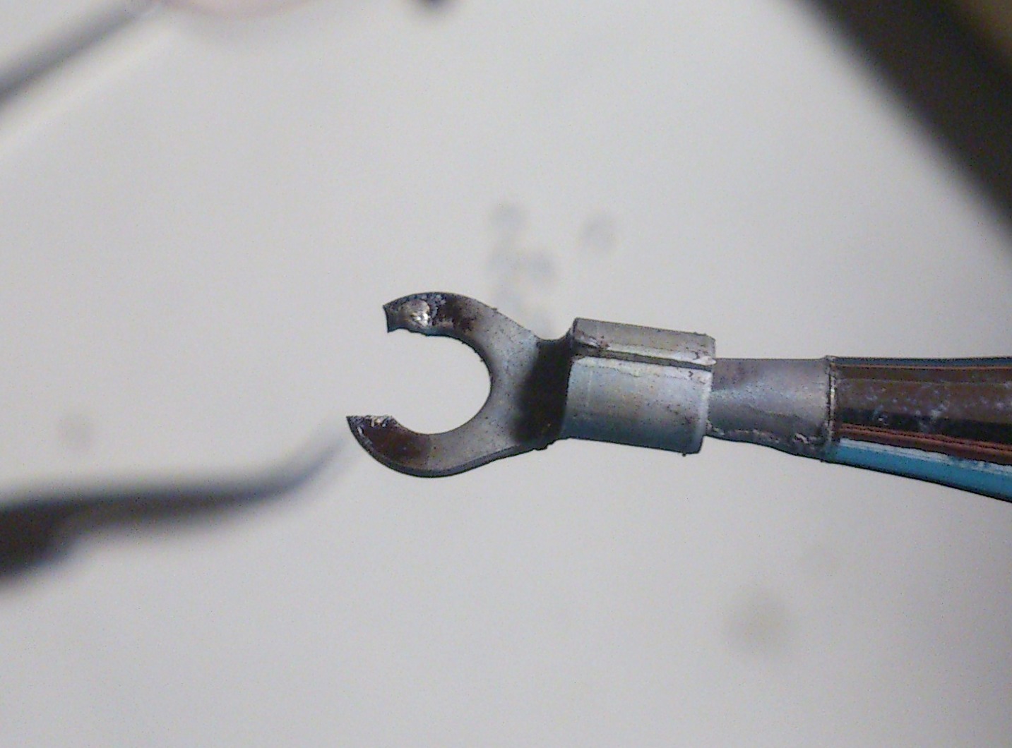
Getting the SMD caps off was a bit of a task with just pointed soldering tips available, but I thought: why not make a special tip for that:
![]()
Yeah, thats a cable lug with a piece cutted out so it fits my capacitors width shoved onto the biggest ttip I had. Worked like a charm. I soldered a new one immediately:
Looks a lot better now. Uploading the bootloader via ISCP. I'm waiting for socket strips now for final assembly.
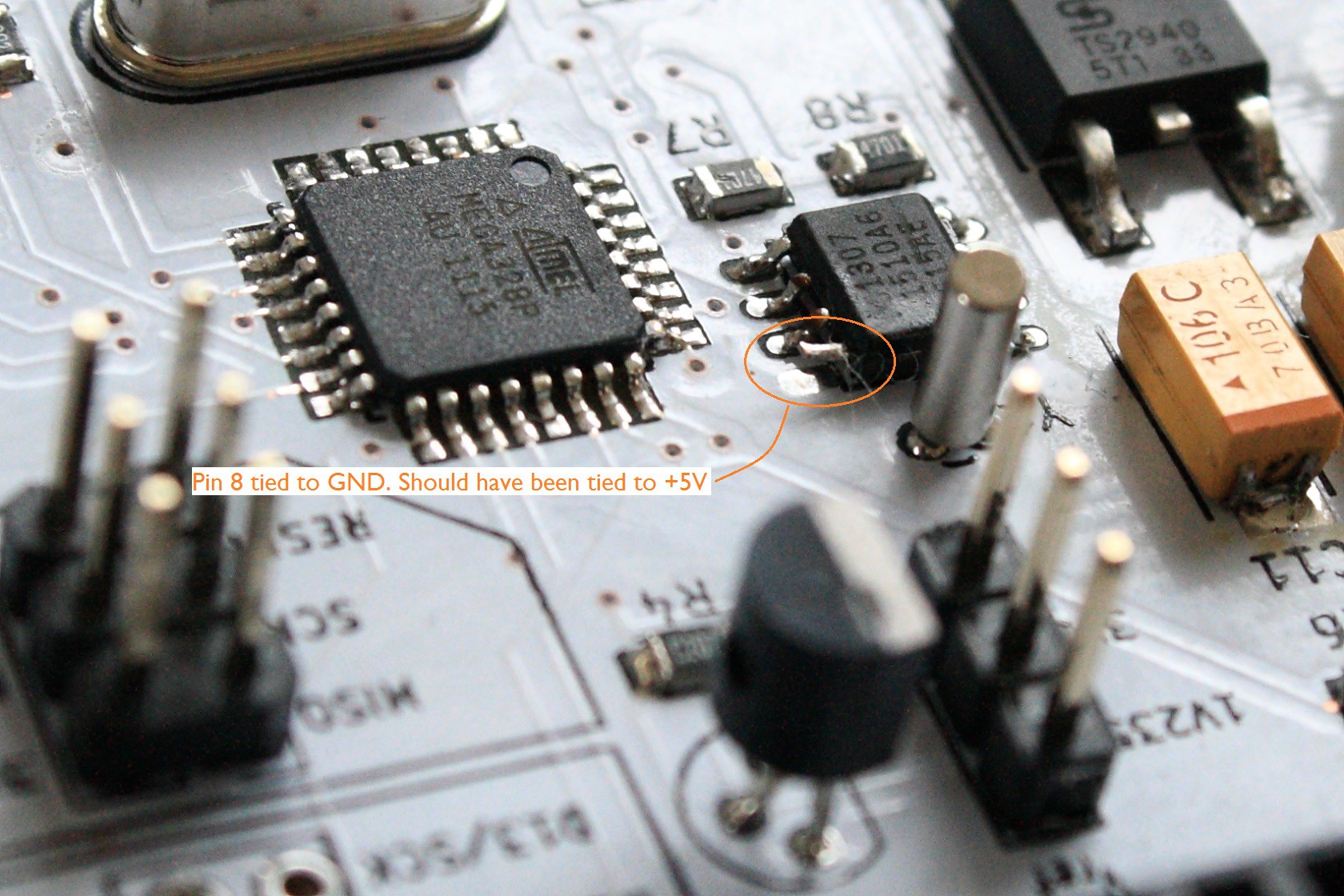
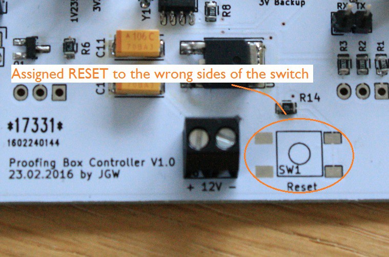
There are two errors on the PCB which I made while designing the circuit:
Error 2:
![]()
Both errors are dumb mistakes, but at least they won't affect the functionality of my PCB.
-
Display impressions
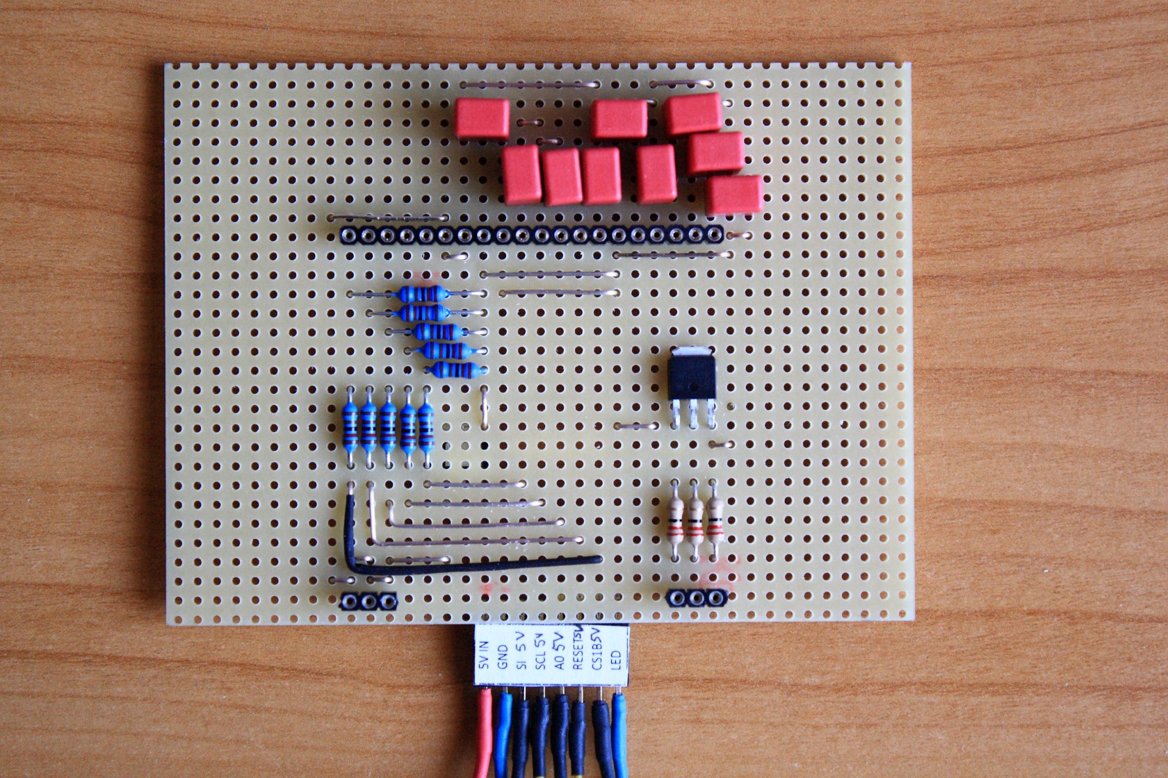
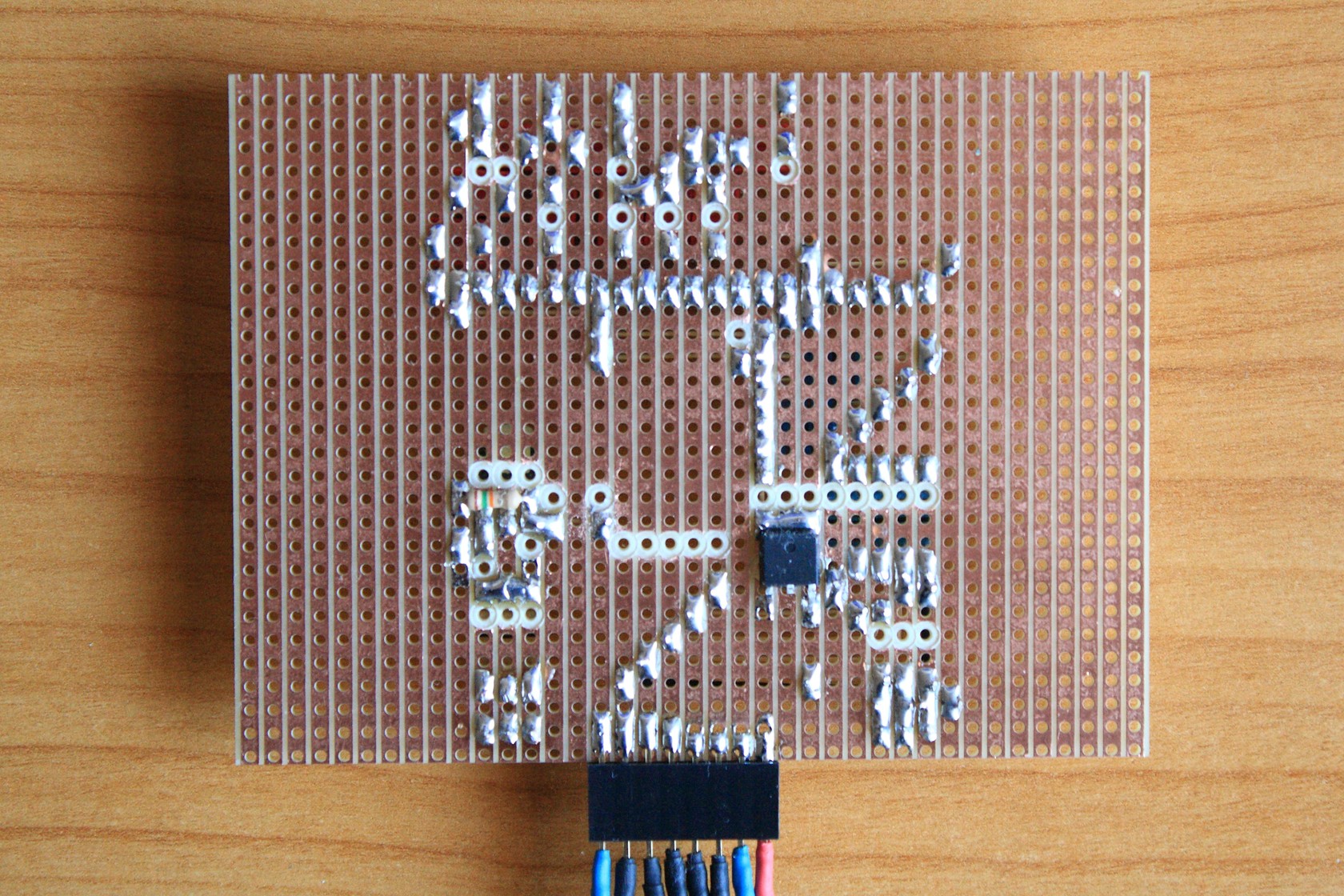
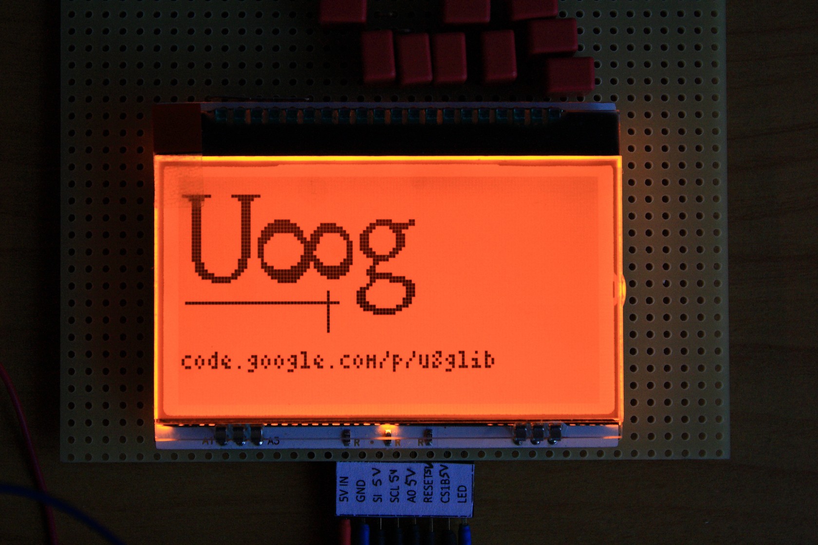
02/28/2016 at 13:44 • 0 commentsOn a lazy saturday evening I had nothing better in mind than hacking together a breakout board for my EA DOGL display. This type does need 9 caps and works with 3V3 only. So I had to add 5 level-shifters (10 resistors).
Top view:
Back view:
Looks a bit botched together, but who cares: Works like a charm. It features a 3V3 VLD voltage regulator and a mosfet which switches all backlight LEDs, which consume 180mA max.
It does work:
-
PCBs: ordered
02/23/2016 at 20:43 • 0 commentsYay! I finished my PCB and ordered them at DirtyPCBs. I hope they'll work like expected and there´ll be no errors in my circuit diagram (checked it a few times).
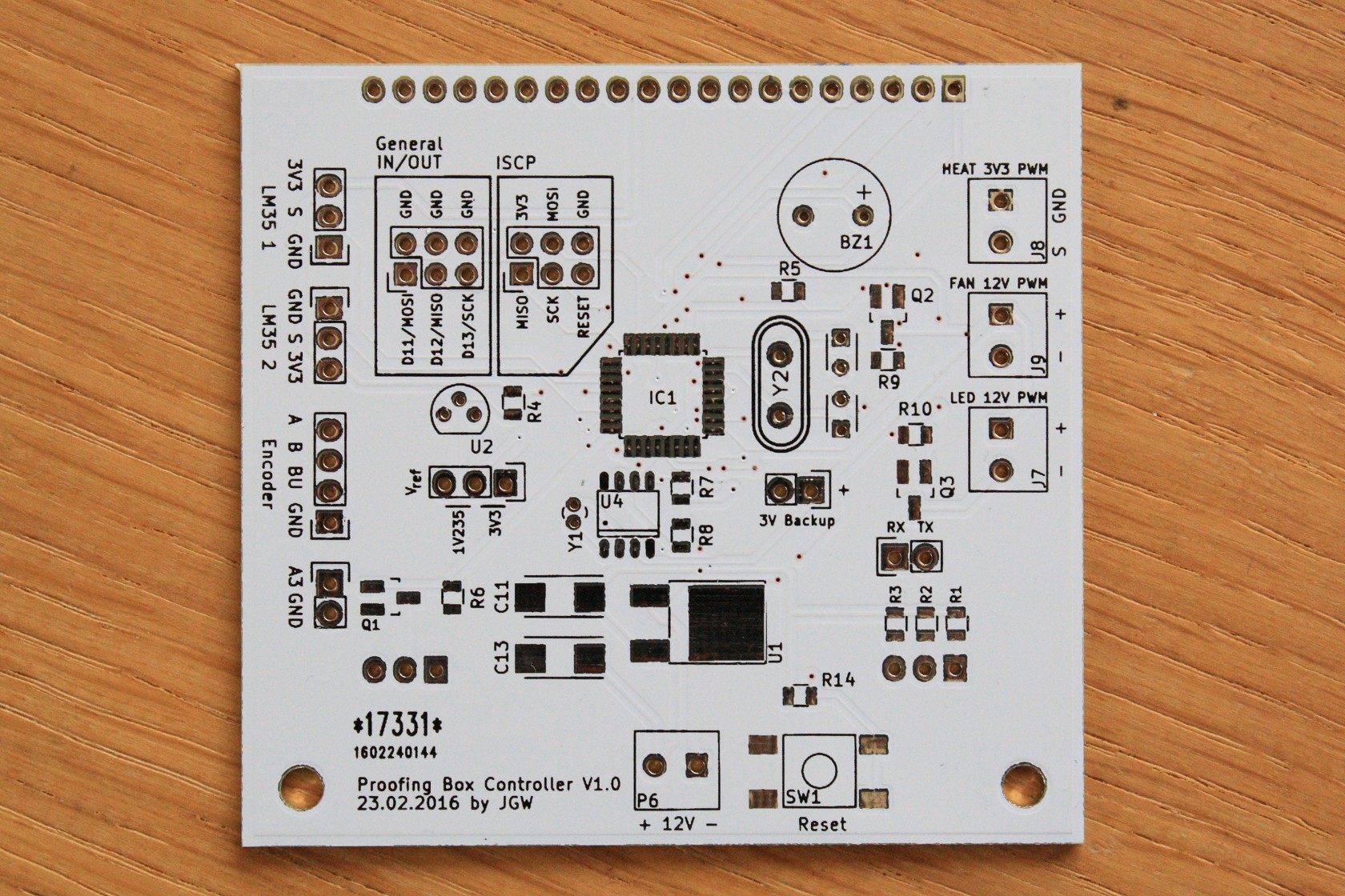
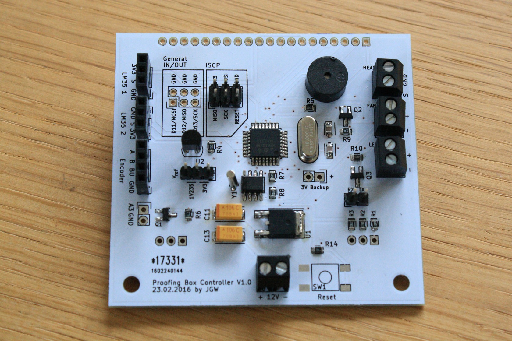
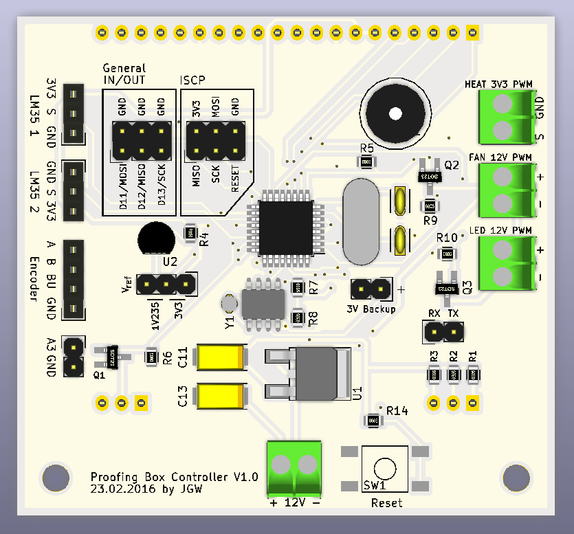
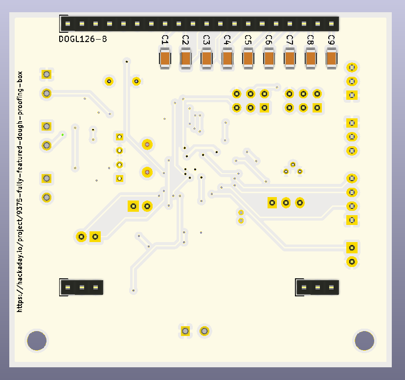
I had to use standard connectors because the WAGO ones were not in stock. I added an ISCP header and broke out RX/TX as well.
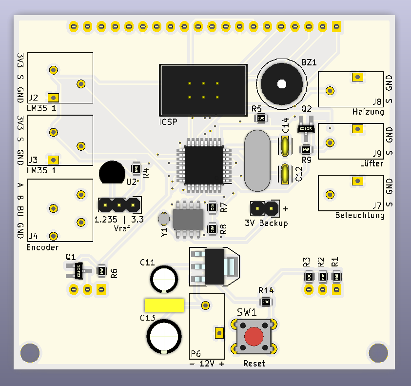
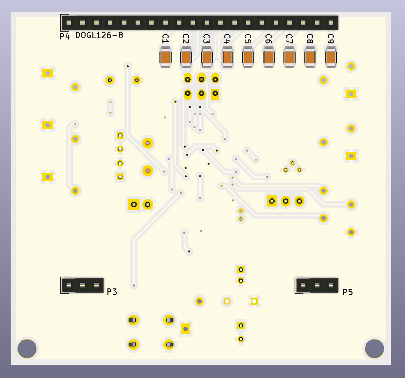
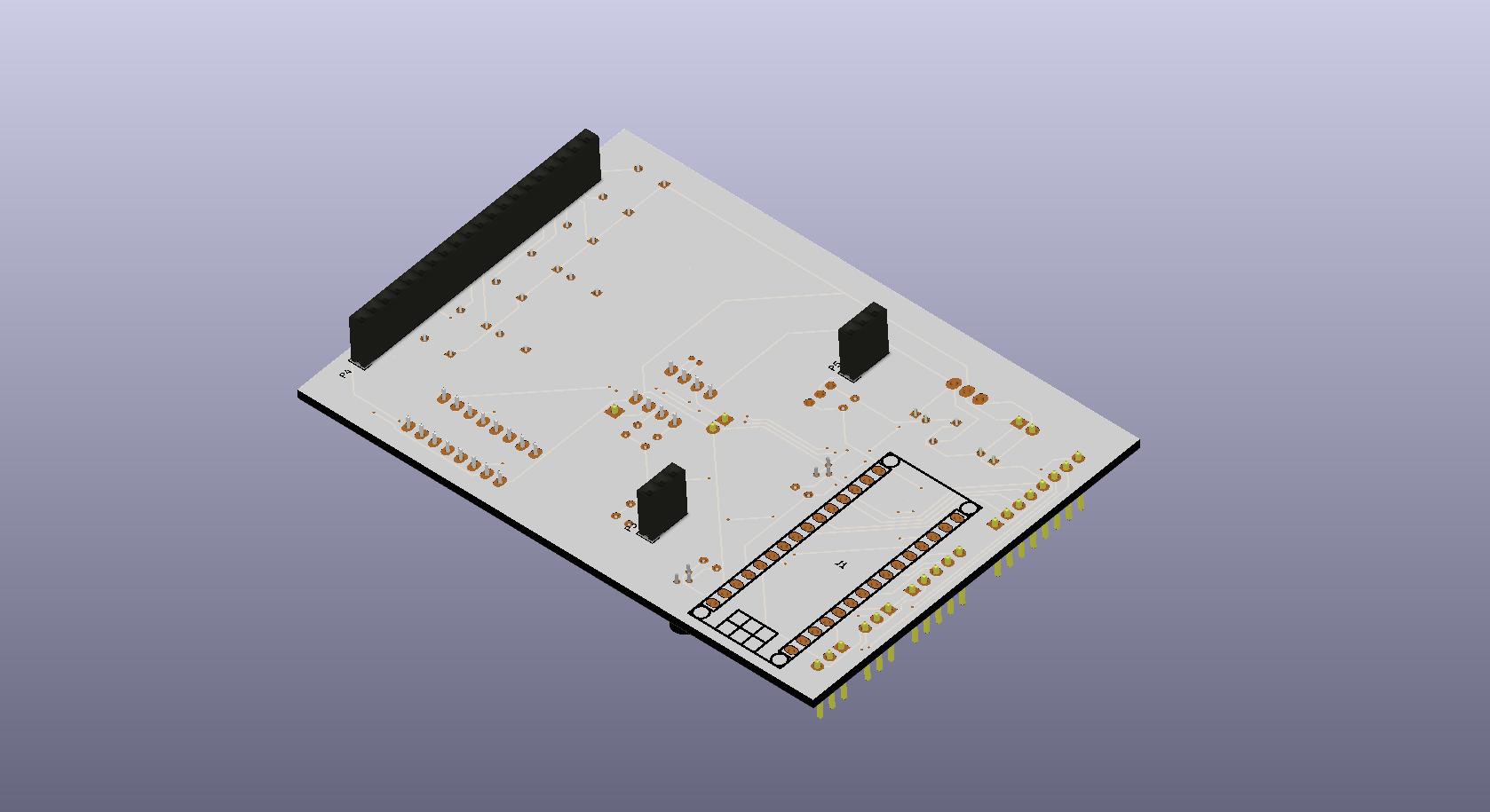
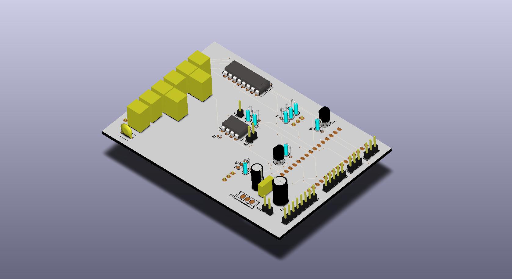
My final layout looks like this (ordered them in white):
![]()
![]()
-
PCB Rev3
02/12/2016 at 18:18 • 0 commentsHi all! Due to space restrictions I switched most of the parts to SMD. The board size went down to 70x70mm (2,78"x2,78"). My goal is to have the PCB ready by sunday.
The front door istn´t as sturdy as expected and gives way especially where the foam gaskets are. I´ll have to think about a sollution for that.
Stay tuned :)
Edit: I finished the PCB. It has got a proper copper fill on both sides now. Here´s the (99%) finished PCB:![]()
![]()
Big changes:
- ditched the Arduino Nano for an standalone Atmega 328
- 3V3 operating voltage -> no level shifter needed anymore
- J2 - J4 and J7 - J9 are WAGO 250 series connectors. Super nice stuff :)
It the silkscreen has to be refined a bit aaaaand I have to add another voltage regulator for 5V output.
-
PCB in progress...
02/07/2016 at 18:12 • 0 commentsI worked a little on my PCB. I Added a additional solder-pad field if I´d ever need to add something to the board.
![]()
![]()
-
First try KiCAD PCB
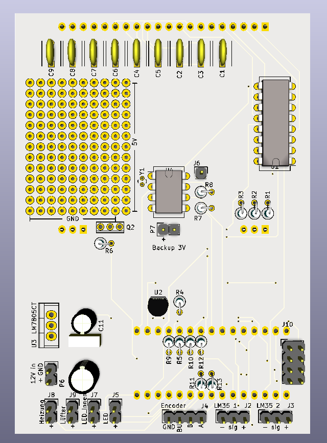
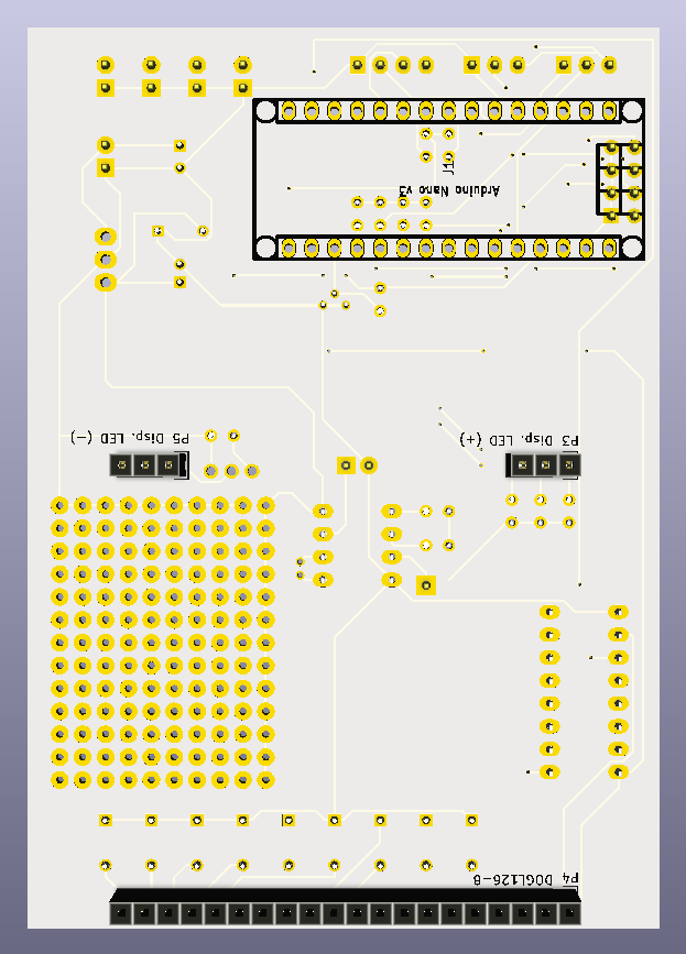
02/06/2016 at 00:00 • 0 commentsToday I finally got around to try the whole KiCAD workflow. Creating a circuit diagram, one or two new footprints and finally routing a PCB.
This is just the first version. Kind of messy and not completely sane design. Display and Arduino Nano v3 go to the bottom side, rest of the parts to the opposite side.
![]()
![]()
There is lots of space left and component placement is far from perfect. Lots of work to do!
Edit: The board is 100x70mm. That´s all I can cram into the space behind my front door...
-
Help needed realising falling temperatures
02/04/2016 at 11:20 • 3 commentsWhile heating is no problem at all, cooling down the system is very tricky. Most sourdough techniques do not need temperatures lower than about 22°C.
In winter thats no problem at all: Warm air could be sucked out of the box with a fan/vent, thus minimum temperature being room temperature or a bit higher.
But in summer, room temperature often rises above 25-28°C. Thats too much for some sourdoughs (e.g. you want to realise a temp. drop from 35°C to 22°C). So active cooling might be required. I thought about peltier elements (cheap, easy to implement), but these need a lot of power (12V, 60-70W). That´d be a tad too much and I´d need a bigger 12V supply...
Does anyone have a good idea on that topic?
Fully featured dough proofing box
A device for maintaining a perfect environment for proofing bread doughs of all kinds.
 Jan
Jan