 Yann Guidon / YGDES
Since this project has forked (giving #Clockwork germanium), this MOSFET project is developed for "educational outreach". For example, I plan to build one version in collaboration with LOREM's "fab kids" to show kids the basics of electronics. From design idea, to prototyping then layout, fabrication, soldering and testing, there are so many things to learn and hack !
Also I'd like to create kits, in through-hole and SMT versions, for individuals and for when I organise workshops for beginners. The modular design is great to teach soldering in small/medium groups.
Many ideas and some techniques are shared with the germanium version (such as the resonator and overall structure) but the MOSFET version is cheaper, draws less current and helps me teach "how things work". People comfortable with the design of this clock might later want to play with the #Discrete YASEP.
Structure
Clock circuits have been rehashed so many times... I have even covered it in a series of french articles that teach VHDL but it's still interesting to examine it. The original version was pretty classic, a bit like transistorclock.com.
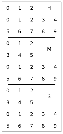
The new version doesn't use 7-segments digits. Instead it directly shows the state of the Johnson counters, thus saving a few hundreds of parts and creating a pretty unusual look. Add to this the 18KHz crystal oscillator (which is very visible and has an unusual frequency) and this clock is now pretty curious :-)
The faceplate looks like this:
The basic elements of the clock are pairs of complementary MOSFET assembled in a reconfigurable flip-flop, called 10TFF, which is used as a LEGO brick for the whole system.
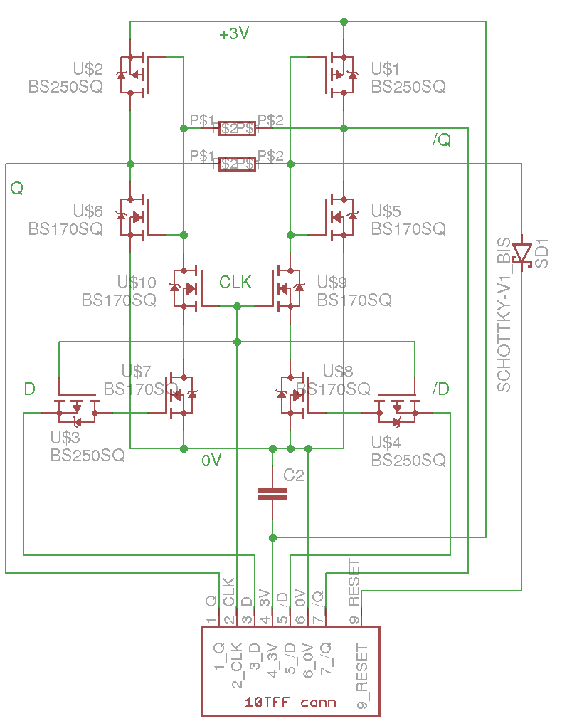
Only these identical modules are needed to build all the counters, and some more transistors perform some glue logic (non-power-of-two counters, reset, alarm...).
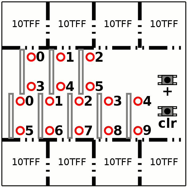
8×10TFF modules are assembled as a HMS board that can be soldered to count 60 or 24 pulses. Three such boards are chained to count the Seconds, Minutes and Hours. One HMS board fits the standard 100mm×100mm unit of PCB manufacturers.
You can drive the seconds' HMS board with a 1pps signal (with sufficient duty cycle) but this project goes beyond that. Another special clock board contains a quartz crystal oscillator, that resonates at 18000Hz, and a ÷5 predivider. The 3600Hz is then fed to a cascade of two HMS boards to lower the frequency to 3600/(60×60)=1Hz. (That's @K.C. Lee's idea btw, which uses more transistors but might be conceptually more educational)
The whole system should look like this when the faceplate is removed:
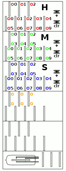
More informations are tucked after the logs.
Logs:
1. MOSFET idiosynchrasies
2. Another inefficient design
3. Enhanced FlipFlop
4. Inventory
5. Cascaded Johnson Counters
6. Crystal oscillator with complementary MOSFETs
7. Power supply voltage
8. To MUX or not to MUX
9. BCD to 7-segments decoder
10. How to divide by two
11. A generalised minimal D-FlipFlop
12. Inventory n°2
13. Midnight reset
14. Another display option
15. Testing the Flip-Flop
16. TODO
17. Integrated 32KHz clock source
18. A faster Generalised Flip-Flop
19. Even better 10TFF
20. The first 10TFF module
21. Debouncing The Smart Way
22. Slow oscillations
23. Oscillators' basics
24. Debouncing in reality
25. Oscillator calibration
26. Dynamic MOS logic
27. Got Quartz ?
28. First 10TFF module
29. Change of architecture
30. Another MOSFET oscillator
31. Yet another MOSFET oscillator
32. The first PCB arrived today !
33. Testing a module
34. It was too easy...
35. My first discrete 5-stages Johnson counter
36. Divide by 15
37. New 10TFF layout
38. The HMS board
39. The KCL structure
40. Testing the KCL structure
41. Crystal oscillator with MOSFETs and LEDs
42. Crystal oscillator with MOSFETs (new episode)
43. Impendance matching for crystal oscillators
44. Success ! a minimalist, single-MOSFET quartz oscillator !
45. Power supply for the quartz oscillator
46. Prescaler mod 5
47. Complete 18KHz source
48. 10TFF module v2
49. 10TFF-v2 received !
50. More minimodules
51. Small signal, high impedance amplifier
52. Teardown of a real watch
.
Tribute
The initial inspiration came as a kid, while I looked at a french popsci magazine that presented a 3D sculpture that works as a clock. Besides the recent events, some other projects here have rekindled the interest in this subject :
- #Relay Logic Clock (I don't thank you, you gave me too many clues and tips to keep the idea in the memory closet)
For the discrete transistor logic let's not forget #The T-1: A discrete 8-bit Stack Computer and #AYTABTU - Discrete Computer but I'll use MOSFET complementary logic instead,
- for the very low power consumption (though the BS170/250 require a higher supply voltage than bipolar which works at 1V)
- it's the technology that is used everywhere today so it has a better "educational value"
- everybody uses BJTs already, such as http://www.transistorclock.com/
Historical reference
Read http://ethw.org/First-Hand:The_First_Quartz_Wrist_Watch
Of particular interest are the schematic of the Xtal oscillator and the divide-by-two stages with integrated bipolar transistors:


Seeing these drawings increased my desire to make my own version!
Some of the tricks and "innovations"
- Complementary MOS logic requires more transistors than bipolar methods but consumes much less current. I've come up with a few hacks to keep the parts count from exploding. They are explained in the logs but what remains is the 10TFF (10-transistor Flip-Flop). This uses a couple of resistors which is not "completely in line" with the project philosophy but it's a reasonable method to reduce the parts count, since current is only drawn during transitions (and it's not a MHz-type design).
- I have also worked extensively to find the best crystal oscillator that uses only MOSFET, is low power, easy to tune and uses the minimum number of parts. The result is presented in log#44.
Applications
One day, I'd love use #Volumetric Circuits! to make my own 3D clock sculpture.
Hopefully it can be turned into educational material, as the next step after #Yet Another Electronic Lampyridae :-)
A germanium version is developed as #Clockwork germanium
.