 Yann Guidon / YGDES
(More oscillators discussions at Oscillators' basics)
Superseded by Crystal Oscillator (Germanium Edition)
I feel as if I just had overcome an old curse.
I made my first 32KHz quartz oscillator run !
*Cue "Chariots of fire" main theme*
This is thanks to the invaluable and inspiring report by Armin H. Frei, LSMFormer Research Staff Member Centre Electronique Horloger. He provided the following schematic :
 This accompanying text is also precious :
A number a different circuits for driving quartz oscillators were
available at the time (Clapp oscillator, etc.), none of them fulfilled
the necessary requirements for our quartz wrist watch: Say no coupling
capacitances, low total resistors value on the chip, tolerance to the
integrated circuits fabrication process and its deviations, rigid
operational stability and low power consumption. This for bipolar IC's,
as well as for low battery voltages. – The newly developed, symmetric
cross coupled driver circuit as shown on the picture incorporates a
minimum of four resistors with pair wise equal values Rc and Re as well as two transistors Tr1 and Tr2
and fullfils the above requirements extremely well. The emitter
resistors serve as current sources and the collector resistors provide
for the negative impedances to drive the quartz. The circuit exhibits a
negative impedance of -2Rc approximately measured between the
contacts 1 and 2. The circuit was very tolerant to various
applications and conditions, and easy to fabricate. It took our
specialists of the semiconductor pilot line, Raymond Guye and his
colleges, less than two months to ship the first fully integrated
properly working chips. The circuit was developed and tested by Armin
Frei in 1965 and 1966.
This circuit is unlike all the others I've seen and it looks reliable, simple, elegant... The key is in the values Rc and Re, which are not provided. So how do I find them ?
My first bet was to use values from the other parts of the circuit, like 1M Ohms, because I thought they didn't want it to draw much current.
So I took a pair of old 2N2222 in metal can, for a more antique feel, and I assembled the following circuit :
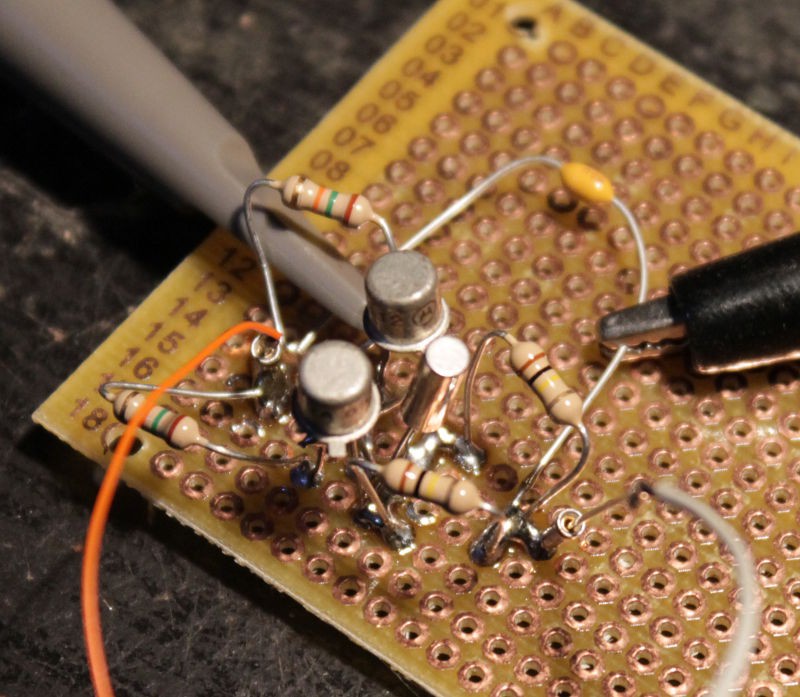
I must have something wrong somewhere. Then I reread the text and noticed the part where the impedance is -2Rc at the Xtal pins. Wait, what's the impedance of a 32KHz Xtal ? After a little websearch, I found approximately 30KHΩ so I set Rc=15KΩ, and Re=100KΩ.
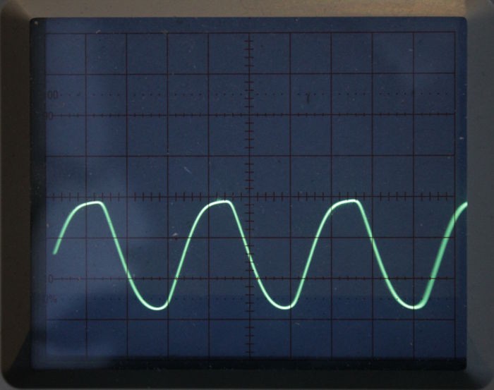
It didn't work right away so I was about to poke around some more, but the 'scope trace was bizarre then the sine wave grew, until it saturated.
This circuit is as described, works at low voltage and the trace has a decent amplitude : 300mVpp at 1.5V and 500mVpp at 3V. It could be higher, but there is an obvious saturation, as shown on the following pictures (1.5V and 3V respectively)

- How do I create a faster startup ? in this video, it takes 23s... Maybe a push-button to 0V could "kick" it ?
- How do I remove the saturation ? What are the appropriate resistor values ?
- What's the difference with Germanium transistors ? I found a pair of 2N396 :-)
- How do I adapt it to N-FET ?
So many questions and so many experiments to find the answers...
Anyway, Armin, if you read me, thank you :-) Tonight I can fall asleep with a smile on my face, thinking : "I have finally made a 32KHz quartz oscillate !"
Update: the startup can be easily forced by a little "kick", indeed, but a mechanical one, just a little vibration is needed to get the tuning-fork to start to oscillate :-D gently hit the circuit with the end of a screwdriver or something like that...
Oscillations last down to 0.9V. I should see how well it compares with N-MOSFET and Ge transistors...
The Re value is important too, as it sets the gain. Setting it to 1M instead of 100K keeps the circuits from starting below 5V. It's indeed, as the text says, a current generator. For enhanced stability and reduced power, the voltage should be kept constant, maybe 2V. A slow oscillator could "kick" the circuit with 3V pulses until it senses the oscillations.
OK, now, how do I make a voltage- and temperature- insensitive regulator out of MOSFETs ? :-D Bipolar bandgaps provide 1.23V ... A TL431 (set at 2.5V) requires up to 1mA to maintain regulation...
Wait, I have some LM4041 which are lower voltage, lower current versions of the TL431 :-) Didn't I say the osc works down to 1V ?
It looks like the LM4041 are ... duds ?
So far, the working parameters are:
- high gain NPN (2N2222, BC548C@Hfe=500)
- Rc=15K, Re=100K
- Xtal is "metal can". No sign of life with plastic, SMD type :-( I must have missed something ?
Germanium transistors (PNP, Hfe=150) didn't work. And a MOSFET version will require serious re-engineering. However, since I got a working system, I can tune it to work with this schematic :

Update (20160404): the LM4041 works so there is a chance to regulate the voltage that drives the oscillator, against temperature and voltage changes. To get the 1.2V, the Vref pin should be tied to GND. This is cool because it controls the output voltage so a positive pulse on this pin will "kick" the oscillator :-)
Powering the BJT-based oscillator with a lower voltage will also "shift" the signal's voltage toward the cross-conduction level of the CMOS input, reducing the need for a DC-blocking capacitor...
Discussions
Become a Hackaday.io Member
Create an account to leave a comment. Already have an account? Log In.
Congratuation!
You know so many times I wish MOSFET can be driven like BJT - sort of the reverse of IGBT. They are fine until you really want to make them run fast and then you have to start looking at gate drivers with huge gate currents.
Are you sure? yes | no
Thanks !
For the MOSFET-BJT thing, I don't know... So far I'm not trying to do high-speed high-power things, I want the circuit to last a long time with a couple of AA batteries :-)
Are you sure? yes | no
haha, comment-depth ;)
Now that you mention it... at the rates our CPUs and stuff are running these days, it almost seems like BJTs would be less current-consuming, at least for the parts that never idle. Interesting.
Are you sure? yes | no
Isn't that kinda like a JFET, or is my memory lacking?
Are you sure? yes | no
http://www.allaboutcircuits.com/textbook/semiconductors/chpt-5/junction-field-effect-transistors-jfet/
>Note how this operational behavior is exactly opposite of the bipolar junction transistor. Bipolar transistors are normally-off devices
>For this reason, we classify the JFET as a voltage-controlled device, and the bipolar transistor as a current-controlled device.
JFET are kinda nice, but rarely found outside of small signals. I want something with a current gain, but MOSFET like switching. I used a hybrid in my LED driver project.
Are you sure? yes | no
You mean, like BiCMOS ?
Are you sure? yes | no
https://upload.wikimedia.org/wikipedia/commons/e/e0/Bicmos_inverter.png
I want the BJT side as the input and MOSFET as output in a discrete part. Everyone want the other way around and we ended up with IGBT - slow but huge current. I suppose when you are making BiCMOS chips, the MOSFET can be made very small gate capacitances so the driving part is easier.
Are you sure? yes | no