 Yann Guidon / YGDES
Using the 18KHz clock source, the cascade of dividers is more complex than with the usual 32768Hz crystals. Normally, 15 stages of division by two (15 flip-flops) bring the 32KHz input down to 1Hz. At 18KHz, a different cascade is chosen:
- divide by 8 (3 flip-flops) : 2250Hz
- divide by 15 (3 flip-flops) : 150Hz
- divide by 15 (3 flip-flops again) : 10Hz
- divide by 10 (5 flip-flops in Johnson counter configuration) : 1Hz
The divide by 8 has already been implemented.
From there the 10-states Johnson counter was rather easy to implement.
Now there is a new logic design problem to solve : how to divide by 15 ?
These divisors have been chosen because they use most of the coding space allowed by 4 bits, only one code is lost out of 16. This is pretty easy to do with a synchronous counter : detect the code 15 (1111) and trigger the reset.
Detecting the code is easy too : just use 4 diodes (or even MOSFET) wired to the right signals, add a pull-up(/down) resistor, and you have a pulse.
The problem is with the reset signal because there are many timing issues with a ripple counter. Some kind of resynchronisation must be performed.
- Either the circuit must be fully synchronous
- Or the reset circuit must be sampled.
The choice will depend of course on the complexity and parts count.
A fully synchronous circuit is possible but implementing the incrementation with discrete MOSFET is going to be too heavy. The ripple counter has this amazing property of avoiding explicit calculations, which saves many parts.
Sampling the reset signal has been done before : The 10TFF cell contains 2 sampling circuit for D and /D, made of one P-FET (a pass-gate) and two N-NET (one charge-memory and one clock-enabled pass gate).
As is, the circuit can't be reused because the body diode of the P-FET will allow the N-FET charge to be removed as soon as one of the 4 FlipFlops is cleared, which might leave the others still in their previous state. The charge must be preserved longer and the parasitic diode must be disabled. This is possible at the cost of one more P-FET in reverse with the data-pass-gate.
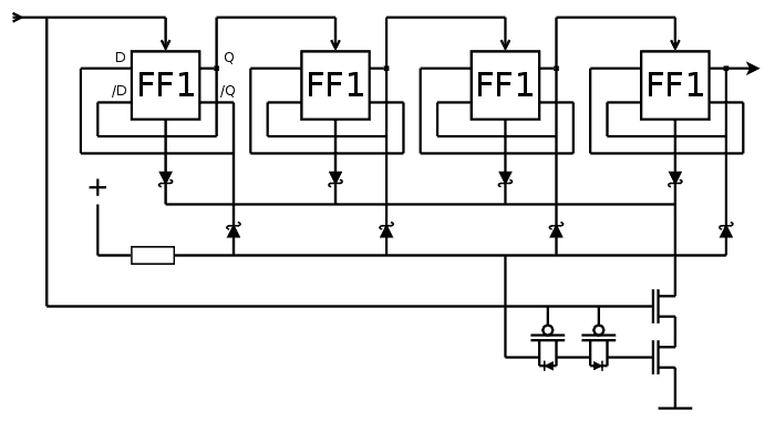
This way, the reset signal will be applied strongly, during one clock phase, with only 4 MOSFET, 4 (more) diodes and 1 resistor...
The fanout of the clock is almost 20 FET gates. This is why there is a 2^3 predivider after the crystal oscillator.
The reset detects code 1110, but this could actually be 111x, so we can save the diode connected to /Q of the leftmost flipflop.
Update (20160519): the power losses through the pull-up resistor can be reduced by enabling the power when the last couple of FF are "ready", through one or two BS250. This would make a diode-transistor logic AND gate...
Discussions
Become a Hackaday.io Member
Create an account to leave a comment. Already have an account? Log In.
If you already have the HMS boards that can count to 60, then
18kHz /5 /60 /60 = 1 Hz
Are you sure? yes | no
That's not false but... "underefficient" because counting to 64 requires 6 flipflops and the HMS board uses 8. For the <1Hz part, there is a compromise because this design saves on the (non-existent) decoding logic.
I admit, I have thrown some "efficiency" out of the window by using one more FF than necessary for the hours, but that's one place.
The other places >1Hz require faster circuits (lower resistors) and a more careful design so I can't use the same FET-saving hacks.
The economics of your solution sounds OK because it reuses only one layout, which is a significant cost, but not the worst.
Also, I'm pretty annoyed that I'd have to make a ÷5 prediv, I have no idea how it can be made efficiently in CMOS, and in logic in general. P-MOS are not really cheap in TO92 :-/
I'll see how to design a board with both the Xtal osc and a ÷5 prediv... Any hint on the structure of the prediv ? It's not a power of two, and not even so I can't use a Johnson counter. Since it's a high-speed part, I'll have play with the gate capacitance to save transistors, vs the larger and slower 10TFF flip-flops.
Are you sure? yes | no
I rarely need to use something other than DFF or synchronous counters. I'll let the HDL compile generate Linear Feedback Register when speed matters.
Are you sure? yes | no
Yep but here, it's not a FPGA and each MOSFET counts... The BS250 are not as cheap as other parts :-/
Thanks for the tip about LFSRs. I used to have a sheet of arbitrary length non-power-of-two generators but I have not seen it since 2001.
Actually, decoding 5 might not be as hard as I thought, it's just a matter of decoding when the state reaches 4 (which is when the MSB is set) and generating the RESET at the next clock cycle...
This only uses 3×10TFF so I have to test it ASAP !
Are you sure? yes | no