 Yann Guidon / YGDES
After I sketched The HMS board, @K.C. Lee made a pertinent remark about another use of these boards for dividing the 18KHz source down to 1Hz.
Two HMS boards divide by 60, each, or 3600. Only a factor of 5 is needed to get 18000Hz. This reduces the overall complexity but increases the parts count (which I have been very careful to keep low... until now).
The other problem is how to implement a ÷5 predivider. I reused the ideas of Divide by 15 to create the following diagram:
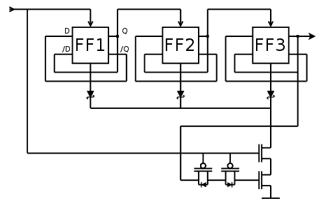
FF1 and FF2 create a divide-by-4 counter and FF3 registers the overflow of FF2. The counter goes through the states 000, 001, 010, 011, 100 then during the next cycle, the latch at the bottom (with a pair of PFET and a pair of NFET) forces the reset during half a cycle. The state should go back to 000.
Actually, FF3 might not be necessary because it's used as a sort of set/reset latch that adds a one-cycle delay. Maybe I can save a few transistors.
In fact no because the latch is synchronous on one edge of the clock signal so at least one "charge pump" is required.
Discussions
Become a Hackaday.io Member
Create an account to leave a comment. Already have an account? Log In.