 Yann Guidon / YGDES
I have no idea if this circuit has been imagined before, Google does not seem to find it or I don't have the right search terms...
OK so a Johnson counter (such as the CD4017) is a "twisted ring oscillator" made of N/2 D-FF stages, followed by a very simple decoding circuit (N×NAND2). I have already professed my admiration and love for this smart, efficient and useful design but I have not yet had the chance to actually modify it.
Each D-FF is made of 2 transparent latches, thus a N-stage Johnson counter is made of N latches.
Each latch uses 8 transistors, a NAND2 uses 4 transistors and I'll design a way to reduce this to 2 transistors. So hopefully, I want to reduce each Johnson stage to (8/2)+2=6 transistors. There are 46 stages so this would amount to about 280 transistors.
The bulk of the saving is possible by
- using only latches, instead of D-FF, for the 3 and 5 stages of the ring counter
- using a multi-phase clocking system instead of a single clock
- sharing common clock signals between the different stages (unit of second, tens of seconds, unit of minute etc.).
Let's look at the most used counter: the units of seconds. It's made of 5 latches named L1, L2, L3, L4 and L5. The ring counter propagates the data in increasing order: from L1 to L2 then L3... then the data is inverted when going back from L5 to L1.
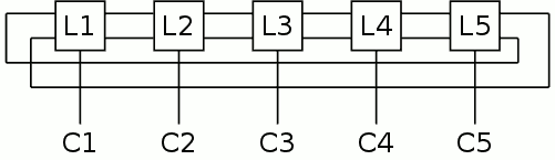
It is obvious that the clock pulse sequence should run in reverse order so the pulse propagates in the right direction in the right rythm: C5, C4, C3, C2, C1
This looks strangely familiar, huh ? Couldn't this come from another decade counter ? Then you understand why I named this circuit "Cascaded Johnson Counter". One disadvantage is that some states might overlap or be disjointed but in our case, it is manifested with a tiny visual jerk.
But this doesn't stop here! In this clock we don't have a source of 5 consecutive pulses but the 32KHz predivider provides an opportunity for binary decoding.
0000
0001 => C5
0010
0011 => C4
0100
0101 => C3
0110
0111 => C2
1000
1001 => C1
1010
1011
1100
1101
1110
1111
This requires 5×AND4, each of them uses 8 transistors, or the number of transistors we saved by using latches instead of D-FF.
Using truncated binary coding, the decoder can be made smaller at the cost of sending two pulses instead of one:
00x1 => C5 (AND3)
01x1 => C4 (AND3)
10x1 => C3 (AND3)
1101 => C2 (AND4)
1111 => C1 (AND4)
This saves some transistors since now 3 ANDs read only 3 inputs instead of 4. This saving can be reinvested in a AND3 of the slowest bits of the counter to reduce the jerk.
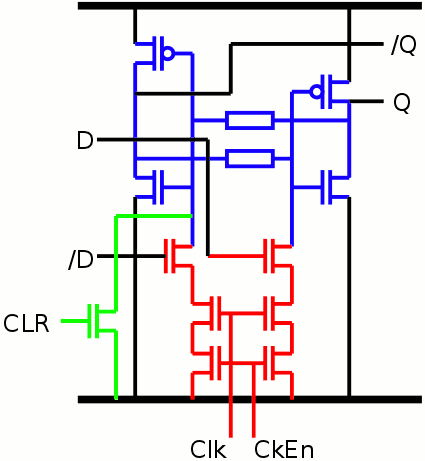
For the tens of seconds, a similar twisted ring uses 3 latches, and 2 AND2, combining the C1, C2 and C3 with the output of the units of seconds. This is only 8+4 transistors instead of 16. The AND2 is a sort of "latch enable" which can be merged in the latch logic and reduced to only 2 transistors. The new latch now uses 10 transistors, plus 2×2 for decoding both associated states, so each state uses 7 transistors. Thus for good measure, I'm adding a reset input.
The gain is similar in the following stages (minutes, hours).
Discussions
Become a Hackaday.io Member
Create an account to leave a comment. Already have an account? Log In.