 Yann Guidon / YGDES
As I design the crystal oscillator, I try to optimise the current consumption. It's not critical for the success of the project but power saving is worth studying and brings insight into today's technology.
In this discrete design, the current draw is mostly due to simultaneous conduction of the P and N FET. I have chosen the 2N7002 and BSS138 references and I created a circuit to measure the unwanted current as I change the power supply's voltage.
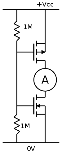
I assume that the maximum current occurs when the common gate's voltage is half-way between 0V and Vcc (I suppose the transistors have a symmetric transfer curve), so I just wired a couple of resistors. This is particularly important since the oscillator is biased with a high value resistor between the gates and the drains.
Then I changed the voltage and measured the current between the drains :
| Vcc (V) | Idrain (µA) |
| 2.5 | 0.3 |
| 2.6 | 0.7 |
| 2.7 | 1 |
| 2.8 | 4.1 |
| 2.9 | 10 |
| 3.0 | 20 |
| 3.1 | 47 |
| 3.2 | 104 |
| 3.3 | 270 |
The amperemeter might not be perfectly accurate at such low values, in part because of the inherent resistance, but I hope that the placement reduced the uncertainty and one interesting trend appears : each tenth of volt multiplies the current by an average of 3. The lower the voltage, the better.
At 3.3V, the current is only one fourth of milliampere, which is not a big problem until the circuit is mutliplied hundreds of times. 3.0V is ten times better so the whole circuit can be reasonably powered by a pair of AA or AAA alkaline batteries or a primary Lithium battery. A CR2032 coin cell is suitable to perform early tests.
The oscillator behaves differently compared to the rest of the circuit: the oscillator is mostly an analog circuit, because of the bias. A significant time is spent with the gates near the highest simultaneous conduction point.
The other circuits are digital and spend very little time in the transition point. One transition might last a hundred nanosecond but only the early stages of the divider oscillate a lot. The Johnson counters rarely change and their dynamic consumption should be very low.
Hopefully, the whole digital design should draw less than 1mA. The display, however, uses LEDs and they will draw a significantly higher current, but that's a different story !
Discussions
Become a Hackaday.io Member
Create an account to leave a comment. Already have an account? Log In.