 Yann Guidon / YGDES
I'm pretty happy about the "optimised Flip Flop" with only one clock input and 16 transistors (and 2 resistors) but the number of MOSFET is still too high: 18×15=270 parts are necessary to divide the 32768Hz frequency down to 1Hz.
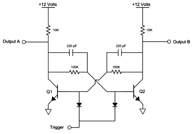
It's not a new problem and it is already solved for the BJT case: see http://ethw.org/First-Hand:The_First_Quartz_Wrist_Watch
 I count 14 parts. The high-side 2.2M resistors can be replaced by MOSFET to further reduce the static current draw.
This principle is also used, in a modified way, by http://www.transistorclock.com/
there are only 10 parts left but this uses diodes and small capacitors.
I have been looking for smaller flip-flops and I've found this:
And another similar circuit by David Johnson:
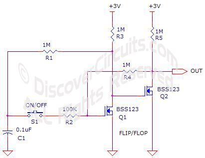 The problem is the dependency on the capacitor's value:
- Too high and the divider will waste power by charging and discharging it
- Too low and the circuit will oscillate, just like in the video above !
Now I realise that a master-slave system is really unavoidable to keep the circuit "static" (not timing dependent) and low power. The precedent state must be preserved while transition occurs. Then I realised a couple of things:
- A MOSFET has a tiny capacitor between the gate and the other pins, that can be "sensed" by the resistance between the drain and the source
- Timing is everything! and I realised that a sort of charge pump was required to isolate the "old state" from the "current state". A couple of pass gates would be activated on opposite levels of the clock signal.
It is thus possible to use the parasitic capacitance of the MOSFET to save one part (or two).
The next question is whether to choose a symmetric or asymmetric topology. In the push-button-latch example, the button lets current go in both ways so an asymmetric (one trigger circuit) topology is easiest.
If the push-button is to be replaced by MOSFETs, the parasitic diode does not let the circuit work and a symmetric design is required, with 2 shorting circuits on both sides.
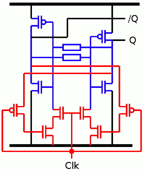
That's 10 transistors, 12 parts !
NB: the clock "pass" transistors are located between the "charge" FETs and the internal loop, hopefully to disconnect the "charge" and prevent capacitive coupling, but this should be further examined.
There is one little gotcha: it can't run at high speed, or else the lower P-FET must be paralleled with a N-FET. The "charge" FETs are discharged through the body diode of the P-FET and this might not be fast enough, or lower the voltage enough. It's a hack !
But if it works, it's a pretty nice one and it should be ok for 32KHz down to a fraction of Hz. There is no static current (yay!) and the charge/discharge current is minimal (equivalent to charging the other MOSFET gates).
12×15=180 : this design saves 90 parts.
If it works.
Discussions
Become a Hackaday.io Member
Create an account to leave a comment. Already have an account? Log In.