 Yann Guidon / YGDES
Following the last log in the series (Yet another MOSFET oscillator) I finally wired the circuit that I imagined at the end of said log.
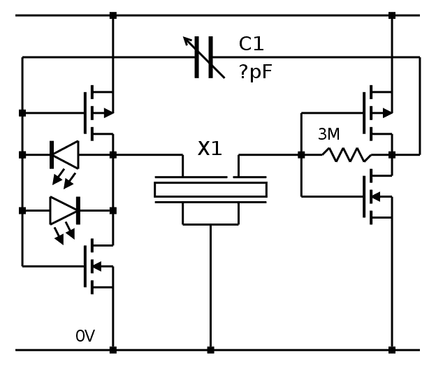
The good news : the LEDs shine when the oscillator is locked, not before.
The bad news : the operating voltage is higher and lock is around 3.6V.
But I think I am onto something... The LED don't act as limiters, contrary to my expectation, but they react well to lock. The light also depends on the C1 feedback capacitor.
Lock is also affected by the feedback resistor (things become interesting around 100K-200K) and it affects the driver's waveform, the LED are fully lit when the output is square-ish.
I need to find a way to lower the working voltage and smooth the waveform. Probably with only BS170s but the BS250 are required for correct biasing.
One solution is to remove one of the BS250 but provide the biasing from the other complementary pair through a very high value resistor (>3MΩ) across the feedback capacitor or the quartz. Assuming that the tempco of all the transistors is the same, only one BS250 is necessary to bias the other BS170s. But which BS250 should be removed ?
- The sense side seems to be a good candidate. In the classical circuits, the crystal is usually in parallel with a very high value resistor to bias the circuit so it should work. An adjustable resistor on the drain will set the gain, which we don't want too high.
- The drive side has the LEDs and its symmetry assures a symmetrical waveform. A feedback resistor is required too, between the drains and the gates.
The parts count shouldn't increase.
I might have found one critical parameter of the crystal : the series impedance might be around 75KΩ. The bipolar circuits work despite mismatch but even with 3 MOSFET, it's very hard and I can't find a configuration that starts up below 3.3V. OTOH the remaining 10TFF act weirdly above 3.1V...
PS: when the quartz is overdriven (like with a full-scale square voltage), I can actually hear the faint whine. It is not only visible, but also audible !
Unfortunately, this emission of energy is not desirable at all.
Ooops, I realize I did all these tests with the 8KHz quartz, not the 18KHz quartz...
Discussions
Become a Hackaday.io Member
Create an account to leave a comment. Already have an account? Log In.
Have you try putting a series resistor between the driver and the crystal to limit the drive?
Are you sure? yes | no
No because this topology is not working as intended and I start to understand why.
I want a circuit that works at about 2V so I can power it with 2.5V, that has a minimal parts count, only MOSFETs, very low drift with temperature (which is helped with minimal parts count), low drive/amplitude for the quartz, low energy.
One thing that helps is that now, I seem to have an estimate of the impendance of the crystal.
Are you sure? yes | no
http://www.crystek.com/documents/appnotes/pierce-gateintroduction.pdf
Are you sure? yes | no
Thanks for the link :-)
I think I have seen this document before.
There is the big question though : is my crystal tuned for parallel or series resonance ? Pierce requires parallel resonance...
Are you sure? yes | no
ah yes it was mentioned there https://hackaday.io/project/9376-yet-another-discrete-clock/log/35190-oscillators-basics
Are you sure? yes | no
My other concern is to reduce the number of parts as much as possible, so there are 1) as few temperature-dependant variations 2) fewer parts to tune and "get right".
So far, two topologies with 2 bipolar transistors seem to work :
(the wristwatch oscillator) and the russian oscillator (found there: http://ua3vvm.qrz.ru/projects/html/gener.htm )
They work quite well with bipolar transistors but their simplicity is hard to translate to a MOSFET system because biasing is totally different.
Are you sure? yes | no
I think I found another method, with a pair of N-MOSFET both in common gate inverter configuration ! I have to try it !
Are you sure? yes | no