 Yann Guidon / YGDES
I think I understand better now.
Many of my failed attempts are due to another condition that I didn't check, and which comes from one fundamental difference between MOSFET and BJT : there is no current going through the gate.
There are two "working" BJT circuits that use a pair of transistors and one in particular works great, even with "lazy" PNP such as the OC70: the "capacitor-coupled amplifier":
 In It just works I reported that the circuit works very well but in Another MOSFET oscillator I saw that it's not possible to translate it directly to MOSFET.
I now see what was wrong with my attempts : the BJT oscillator lets signal/current flow through the crystal, thanks to the current path from base to emitter. When I use MOSFETs, something is missing, the "driver" transistor "shakes" on pin of the crystal but the other pin is floating and can't let the equivalent LC network oscillate. No energy is input because the other pin is floating and no energy goes out.
More important : the equivalent resistance, the impedance, is critical to allow the oscillations. All the crystal oscillators I've tried start to oscillate, or oscillate better, when one of the resistances is at a very particular value. It's the impendance matching part of the equation.
In the classic Pierce oscillator with inverter, the impendance is set with a series resistor and the two "parallel" capacitors. The last capacitor (connected to the inverter's input) is the critical one, which connects the signal to the ground so the crystal doesn't dangle in the void. My error becomes pretty apparent in the log Crystal oscillator with complementary MOSFETs where the capacitor is missing, the crystal pin is virtually dangling with no return path for the current !
So now, one design parameter or constraint is : the resonating element is not only the crystal, but also a resistor in series with the crystal.
- One of the parts is connected to a stable voltage, such as ground (ideally) or Vcc.
- The other end is connected to the "driver" transistor's output
- The middle point is where the "sense" gets the signal.
Let's add that the circuit must work under 3V and use a minimal number of parts, the new trick is to integrate the series resistor in the biasing network of the transistors. Naturally this leads to funky circuits with common gate or common drain configurations.
However common drain configurations have a voltage gain less than one. I somehow came up with this strange common-gate configuration:
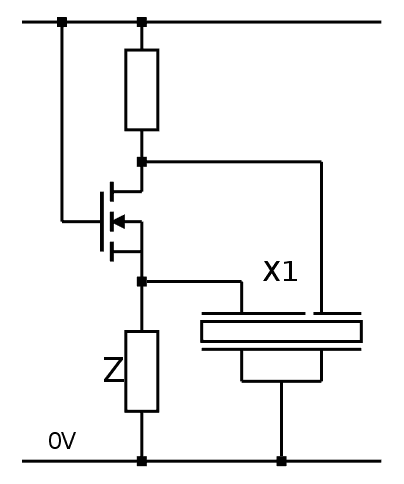
(erratum: the crystal is wired in reverse... Sleep or hack, but don't do both)
(yes, I understand now that this can't work as is but it's a start)
According to some sources, the common gate configuration is a non-inverting voltage amplifier. The input comes from the source, where the Z resistor (impendance matching) is tied to the ground. X1 is also connected to the drain, which is the output node.
I'm not sure at all that it will work but it could... and if it doesn't, I can still try with cross-coupled pairs. Actually, Z also gets current when the MOSFET is conducting, which increases the input and "degenerates" the output. The driving strength would be lower than the typical common source, which also amplifies the current.
Since there is only one transistor (not a complementary pair), the working voltage would be in the 2-3V ballpark, depending on the resistor values.
Discussions
Become a Hackaday.io Member
Create an account to leave a comment. Already have an account? Log In.
Your xtal is 8kHz? I bet you could analyze it with a soundcard. I'll post something, maybe a mini-project, although it might have to wait until next week.
Are you sure? yes | no
8KHz for germanium (because the OC70 are really slow) and 18KHz for the MOSFET.
The soundcard could work but i'm not sure of 18KHz.
Are you sure? yes | no
I have a 96kHz soundcard; they're not too expensive. You might even be able to do a 32.768kHz xtal with it. 192 kHz soundcards are also available. Higher sample rates are popular with the SDR crowd.
Are you sure? yes | no
I have 48KHz sampling and probably 96 somewhere but the input filters certainly attenuate the data. Sampling rate is not the same thing as bandwidth :-)
Are you sure? yes | no
Update : I guess the question is now pointless since the circuit actually works :-D
Are you sure? yes | no
Yann, have you tried measuring the crystal motional parameters? I wrote some code a few years ago to extract an LCR equivalent model for HF crystals from spectrum analyzer / tracking generator sweeps. It used non-linear optimization to fit the data, and with a bit of coaxing, usually converged to a decent model. I found subsequent SPICE simulations of filters made from the crystals pretty accurate, and I assume oscillator modeling would also work (as well/poorly as oscillator modeling does in SPICE). I can dig around for the code, if you're interested.
Are you sure? yes | no
Thanks Ted !
that would be interesting to see/understand, though I'm not sure I have the necessary tools. I just have oscilloscopes and no computer-controlled oscillators (yet.... must still make one)
Now these crystals are not HF, work at much lower frequency, have much more inertia (because they are larger), different cut and resonance modes... It even has a 3rd pin :-D
Feel free to explain your methodology in one of your personal pages, for example :-)
Are you sure? yes | no