 Roman
RomanMeasuring low currents in presence of noise can be a challenge. In my device I use basic current sense configuration with a 1 Ohm shunt resistor and a differential amplifier feeding a 24 bit converter. The differential amplifier is set to gain = 1 to minimize noise and non-linear distortion.
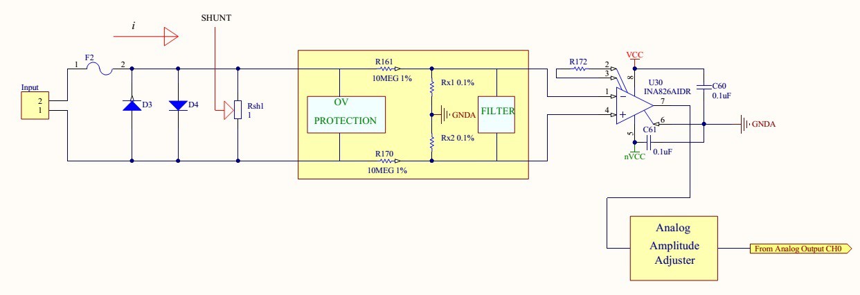
RF coupled noise in magnitude of a fraction of a millivolt distorts readings and causes fluctuation in hundreds of micro amps. Since noise creates outlier values some basic statistical analysis can applied. Taking average of a large number of readings helps to estimate measured value, but the arithmetic mean is affected by all of the data, not just any selection of it. This is a good characteristic in most cases, but it is undesirable if some of the data are grossly in error, such as ?outliers? that are appreciably larger or smaller than they should be. Median values reduces fluctuation and helps to compute an accurate reading. If all the items with which we are concerned are sorted in order of increasing magnitude (size), from the smallest to the largest, then the median is the middle item. Consider the five items: 12, 13, 21, 27, 31. Then 21 is the median. If the number of items is even, the median is given by the arithmetic mean of the two middle items. Consider the six items: 12, 13, 21, 27, 31, 33. The median is (21 + 27) / 2 = 24.
Step 1 - take average of 2048 samples
Step 2 - record 10 averages
Step 3 - compute mean value of 10 averages.
The following code snippet computes a mean value of 10 averages:
if (cntr < 10){
    vals[cntr] = voltage_val;// Collect data.
    cntr ++;                 // Global data counter
}
else{
    cntr = 0;
    for(i = 0; i < 10; i++) {// Calculating mean of 10 numbers
        for(j = i+1; j < 10; j++) { // j is the next element of i
                if(vals[j] < vals[i]) { // if(vals[i+1] < vals[i])
                    temp = vals[i];
                    vals[i] = vals[j];
                    vals[j] = temp;
                }
            }
        }

        voltage_val = ((vals[4] + vals[5]) / 2);
Computing mean of 10 average values reduced readings fluctuations from +/-0.5mA to +/-0.06mA, which is a major improvement.
Discussions
Become a Hackaday.io Member
Create an account to leave a comment. Already have an account? Log In.
MAX4239 Ultra-Low Offset/Drift opamp used in uCurrent - A Professional Precision Current Adapter for Multimeters.
https://www.maximintegrated.com/en/products/analog/amplifiers/MAX4239.html
https://www.eevblog.com/projects/ucurrentoriginal/
This part is what I am considering. It requires a longer recovery time when saturated (ms) instead of (us) in regular opamp.
Not sure how the more link gets in.
Are you sure? yes | no
Something is terribly wrong here. When I tried to click on "more" link in your comment, just got an error page.
Yes, mainly Dave Jones's uCurrent was inspiring me here and my bad experiences of the thermal drift of the resistor in my electronic load project: https://hackaday.io/project/9335-micropower-electronic-load
Actually plenty ultralow Offset/Drift opamps exists on the market, what can be used here:
TI TLC2652, TLC2654, Intersil ICL7650S just to name a few
Even TI has a Zero Drift line of products:
http://www.ti.com/lsds/ti/amplifiers-linear/precision-amplifier-products.page#~p1342=Zero Drift
Are you sure? yes | no
TI parts have lower Bandwidth Gain: 3MHz vs Maxim's 6MHz. Might not be a consider here, but I want to get to higher gains.
Are you sure? yes | no
@K.C. Lee:
Check this:
http://www.ti.com/lit/ds/symlink/lmp2021.pdf
It has 5MHz GBW
Are you sure? yes | no
Thanks. That part looks good too.
Are you sure? yes | no
Hi SUF, very cool project https://hackaday.io/project/9335-micropower-electronic-load. I could use you device to test my current sensor.
Are you sure? yes | no
Very nice amplifier. I think I am to fixated on Analog Devices and TI products, completely forgot about Maxim.
Are you sure? yes | no
Maxim has good products, but there were inventory/lead time issues so I try to avoid using their parts for products if there are no alternate replacements. Not sure if that's been changed.
I am more used to TI parts, but they changed their sample policy for hobbyists and I no longer have local contacts. SUF's TI part actually looks good too and it has much faster recovery time.
Are you sure? yes | no
@K.C. Lee: Yes, I experienced the sample policy change at TI. :-(
But on the other side many of the local and reachable suppliers (unfortunately Digikey and Mouser aren't option here on small orders because of the shipping cost) keep them on stock, and even you can still order anything from TI directly (on affordable shipping cost).
Are you sure? yes | no
Thanks for posting the links, It is probably ok to have longer recovery time because I am talking current reads at 3.6 ksps.
Are you sure? yes | no
It is just a very basic concept for the auto-ranging input, but maybe useful. Haven't tried it, clearly needs additional components and better analog switch than the 4066:
Are you sure? yes | no
You could mux the input of the amplifier. There are analog mux designed for muxing diff inputs for DAS application. Some have input protection.
Are you sure? yes | no
I haven't seen those. If you have a link to the analog mux can you post it?
Thank you.
Are you sure? yes | no
https://www.maximintegrated.com/en/products/analog/analog-switches-multiplexers/low-voltage.html
http://www.ti.com/lsds/ti/switches-multiplexers/analog-mux-demux-products.page
There are also the old logic chips: 74HC4051 - 4053.
Are you sure? yes | no
It would be great. If you can come up with a solution and share it I will be happy to discuss it. I like your ideas.
Are you sure? yes | no
Hi, the circuit looks good. I did not think about using an analog switch at the output. I like the idea. The only thing is that I use the same input, on your schematics labeled P?, for voltage and current measurements. P? could be connected to a high potential (220VAC). I am considering to make "current sense" as a separate channel and use your idea.
Thank you.
Are you sure? yes | no
Thank you for the links.
Are you sure? yes | no
Surely not. Don't forget the protection diodes!
There are circuit designs exists for auto-ranging voltage measurement. If you need, I can come up with something, but mixing the current and voltage jacks not really seams like a good idea.
Are you sure? yes | no
Hi Roman,
I see some problems with this shunt configuration. Using 1 ohm resistor here as shunt way much high. It will lead to various problems in a precision measurement:
- You will get maximum 1A range on the resistor, but it is effectively 0.6-0.7A as around 0.6-0.7V one of your protection diodes will start to conduct.
- At 1A you get 1V burden voltage, what is way to much for many DUT
- At 1A your resistor will dissipate 1W, means it will heat up substantially and the TC of the resistor will ruin your day
- I don't see the type of the protection diode you chosen, but it can have even a few uA reverse leakage current, what also can lead into problems
- If you want to go down to uA range the offset voltage/offset voltage drift of the INA826 also can cause trouble. I would choose some zero-drift type or even a chopper
Cheers,
SUF
Are you sure? yes | no
You are absolutely right, current range is very limited to only 0.5A. The reason is that the instrument is fully automated. I couldn't come up with a simple enough system to switch between different current shunts without using a mechanical switch. I decided to use 1 Ohm thinking it would allow me to do my measurements in mA range. I hope I can come up with a solution that will get to uA range.
I do see about 0.7 mV offset in the channel. It is my whole circuit not just the amplifier. I am using the same channel for voltage and current measurements to lower the unit cost. Offset is a problem that I am hoping to fix with a calibration system. As long as the offset voltage does not change with temperature I should be able to null it more or less. I working on a calibration program.
Thank you for your comments and recommendations. I probably should look for an amplifier with lower offset anyway. I didn't install the diodes, to protect my shunt resistor I take a quick voltage measurement across the shunt and if it is higher then 0.5V I switch back to voltage measurements with an Overcurrent warning message on my LCD display.
Thanks, very good input.
Are you sure? yes | no