 Roman
RomanI am currently working on the Digital Sniffer. The following image show the interface schematics.
Expansion Port:
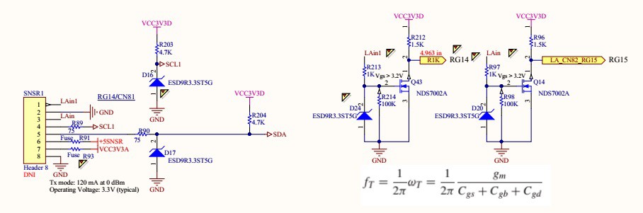
MCU:

Interrupt is initialized inside init_logic_analyzer() function.
PIC24FJ256GA110:
// <editor-fold defaultstate="collapsed" desc="Initialize CN82 on RG15 Interrupt">
    CNEN6bits.CN82IE    	= 1; // Enable interrupt on CN82 RG15 2N7002
    CNPD6bits.CN82PDE   = 0;    	// Pull down disable
    CNPU6bits.CN82PUE   = 0;    	// Pull up disable
    CNEN6bits.CN81IE    	= 1;    	// Enable interrupt on CN81 RG14
    CNPD6bits.CN81PDE   = 0;    	// Pull down disable
    CNPU6bits.CN81PUE   = 0;    	// Pull up disable
    IEC1bits.CNIE       	= 1;    	// Enable interrupt on pin change
    IFS1bits.CNIF       	= 0;    	// Clear the flag
    IPC4bits.CNIP       	= 4;    	// Interrupt priority 4
    // </editor-fold>
    flags = 13;         // Indicates that the Logic Analyzer has been initialized.
    return;
}
Once interrupt is initialized it is ready to read input fromSNSR1 PIN1.
OSCILLATOR data:
Primary oscillator = 7.3728MHZ
Phase Lock Loop:
XTPLL = 4 x PLL = 7.3728MHZ x 4 = 29.4912MHz
FCY = XTPLL/2 = 14.7456MHz. FCY is defined as XTPLL/2
The processor clock source is divided by two to produce the internal instruction
cycle clock, FCY.
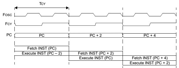
TCY = 1 / FCY = 1 / 14.7456MHz = 0.067817 us
INTERRUPT PROCESSING TIMING
Figure 8-3 shows the sequence of events when a peripheral interrupt is asserted during a
one-cycle instruction. The interrupt process takes four instruction cycles. Each cycle is numbered
in Figure 8-3 for reference.
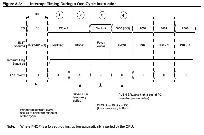
The interrupt process takes four instruction cycles.
TINTERRUPT = TCY * 4 = 0.067817 * 4 = 0.271 us
FMAX-INTERRUPT = 1 / 0.271 us = 3.69 MHz
Each instruction has Fetch and Execute parts. It takes TCY
for each instruction (oscillator).
It looks like I have 16 - 17 instructions in the ISR, then
T = TINTERRUPT + 17 * 0.067817 = 1.017 us + 0.271 us = 1.363us
Max input data-stream frequency is:
FDATA = 1 / 1.363 = 0.7 MHz
I have tested Multimeter+ with max frequency of 500 kHz. Its kind of slow for a logic Analyzer, but for a regular multimeter it adds value.
The following code triggers on every CIN interrupt and shifts in a bit of data.
// Global
volatile WORD_VAL timer[8];
extern volatile unsigned int  TMR1 __attribute__((__sfr__));
volatile DWORD_VAL NmbrOfBits;
volatile WORD_VAL TimeBase;
volatile unsigned long ints;
volatile unsigned char mask_l;
void __attribute__((interrupt, no_auto_psv)) _CNInterrupt(void){
    // Time interval = Number of counts * Time of one count
    timer[0].Val = (WORD)(TMR1 * 68);
    NmbrOfBits.Val = timer[0].Val / TimeBase.Val;
    TMR1 = 0;
    if (LAcntr < 2048){
        if (NmbrOfBits.Val == 0){
            goto skip;          // Skip all
        }
        else if (NmbrOfBits.Val == 1){                       // 7 bits left
                // Input is inverted !_RG14 is actually _RG14.
                // If RG15 is low set current bit to zero with mask_h = 0xFE
                if (_RG14) {
                    voltage_msb[LAcntr] = mask_h;  // mask_h  is initialized to 0b1111 1110
                } else { // If RG15 is high set current bit to one with mask_h = 0x01
                    voltage_msb[LAcntr] = ~mask_h; // ~mask_h = 0b0000 0001
                }
        }
        else if (NmbrOfBits.Val == 2){
                // <editor-fold defaultstate="collapsed" desc="2 bit">
                mask_h = mask_h << 1; // 1111 1110 << 1 = 1111 1100
                // Input is inverted !_RG14 is actually _RG14.
                // If RG15 is low set current bit to zero with mask_h = 0x0b11111100
                if (_RG14) {
                    voltage_msb[LAcntr] = mask_h;  // mask_h << 1  = 0b1111 1100
                } else { // If RG15 is high set current bit to one with mask_h = 0x01
                    voltage_msb[LAcntr] = ~mask_h; // ~mask_h << 1 = 0b0000 0011
                }
                // </editor-fold>
            }
            else if (NmbrOfBits.Val == 3){
                // <editor-fold defaultstate="collapsed" desc="3 bit">
                mask_h = mask_h << 2; // 1111 1110 << 2 = 1111 1000
                if (_RG14) { // Input is inverted !_RG14 is actually _RG14. If RG14 is low set current bit to zero with mask_h = 0x0b11111100
                    voltage_msb[LAcntr] = mask_h;  // mask_h  << 2 = 0b1111 1000
                } else { // If RG15 is high set current bit to one with mask_h = 0x01
                    voltage_msb[LAcntr] = ~mask_h; // ~mask_h << 2 = 0b0000 0111
                }
                // </editor-fold>
            }
            else if (NmbrOfBits.Val == 4){                  // 0000 0001 << 4 = 0001 0000
                // <editor-fold defaultstate="collapsed" desc="4 bit">
                mask_h = mask_h << 3; // 1111 1110 << 3 = 1111 0000
                if (_RG14) { // Input is inverted !_RG14 is actually _RG14. If RG14 is low set current bit to zero with mask_h = 0x0b11111100
                    voltage_msb[LAcntr] = mask_h;  // mask_h << 3  = 0b1111 0000
                } else { // If RG15 is high set current bit to one with mask_h = 0x01
                    voltage_msb[LAcntr] = ~mask_h; // ~mask_h << 3 = 0b0000 1111
                }
                // </editor-fold>
            }
            else if (NmbrOfBits.Val == 5){                  // 0000 0001 << 5 = 0010 0000
                // <editor-fold defaultstate="collapsed" desc="5 bit">
                mask_h = mask_h << 4; // 1111 1110 << 4 = 1110 0000
                if (_RG14) { // Input is inverted !_RG14 is actually _RG14. If RG14 is low set current bit to zero with mask_h = 0x0b11111100
                    voltage_msb[LAcntr] = mask_h; // LAcntr is incremented when byte of data has been shifted
                } else { // If RG14 is high set current bit to one with mask_h = 0x01
                    voltage_msb[LAcntr] = ~mask_h; // Turn on bit zero (mask_l = 0x01). If the first bit is one save one in voltage_msb[0] bit 0
                }
                // </editor-fold>
            }
            else if (NmbrOfBits.Val == 6){                  // 0000 0001 << 6 = 0100 0000
                // <editor-fold defaultstate="collapsed" desc="6 bit">
                mask_h = mask_h << 5; // 1111 1110 << 5 = 1100 0000
                if (_RG14) { // If RG15 is low set current bit to zero with mask_h = 0x0b11111100
                    voltage_msb[LAcntr] = mask_h; // LAcntr is incremented when byte of data has been shifted
                } else { // If RG15 is high set current bit to one with mask_h = 0x01
                    voltage_msb[LAcntr] = ~mask_h; // Turn on bit zero (mask_l = 0x01). If the first bit is one save one in voltage_msb[0] bit 0
                }

                // </editor-fold>
            }
            else if (NmbrOfBits.Val == 7){                  // 0000 0001 << 7 = 1000 0000
                // <editor-fold defaultstate="collapsed" desc="7 bit">
                mask_h = mask_h << 6; // 1111 1110 << 6 = 1000 0000
                if (_RG14) { // If RG15 is low set current bit to zero with mask_h = 0x0b11111100
                    voltage_msb[LAcntr] = mask_h; // LAcntr is incremented when byte of data has been shifted
                } else { // If RG15 is high set current bit to one with mask_h = 0x01
                    voltage_msb[LAcntr] = ~mask_h; // Turn on bit zero (mask_l = 0x01). If the first bit is one save one in voltage_msb[0] bit 0
                }

                // </editor-fold>
            }
            else if (NmbrOfBits.Val == 8){                  // 0000 0001 << 7 = 0000 0000
                // <editor-fold defaultstate="collapsed" desc="8 bit">
                mask_h = mask_h << 7; // 1111 1110 << 7 = 0000 0000
                //mask_l = mask_l << 8;
                if (_RG14) { // If RG15 is low set current bit to zero with mask_h = 0x0b11111100
                    voltage_msb[LAcntr] = mask_h; // LAcntr is incremented when byte of data has been shifted
                } else { // If RG15 is high set current bit to one with mask_h = 0x01
                    voltage_msb[LAcntr] = ~mask_h; //Turn on bit zero (mask_l = 0x01). If the first bit is one save one in voltage_msb[0] bit 0
                }

                // </editor-fold>
            }
            else { // If time lapse is more then 8 bit
                //mask_l = mask_l << 8;                     // Indicate full byte has been received
                mask_h = mask_h << 7;                       // This will indicate that a full byte has been received
                if (_RG14) {                                // If RG15 is low set current bit to zero with mask_h = 0x0b11111100
                    voltage_msb[LAcntr] =  mask_h;     // LAcntr is incremented when byte of data has been shifted
                } else {                                    // If RG15 is high set current bit to one with mask_h = 0x01
                    voltage_msb[LAcntr] = ~mask_h;     // Turn on bit zero (mask_l = 0x01). If the first bit is one save one in voltage_msb[0] bit 0
                }
                LAcntr++;               // Increment byte count
                mask_h  = 0xFE;         // Reset mask for the new byte
                //mask_l  = 0x01;         // Reset mask for the new byte
                if(NmbrOfBits.Val > 8){
                    NmbrOfBits.Val = NmbrOfBits.Val - 8;
                    goto start2047;
                }
                else
                    mask_h == 0x00;     // Exit to if (mask_l == 0x00)
            }


}
Discussions
Become a Hackaday.io Member
Create an account to leave a comment. Already have an account? Log In.