 Gary
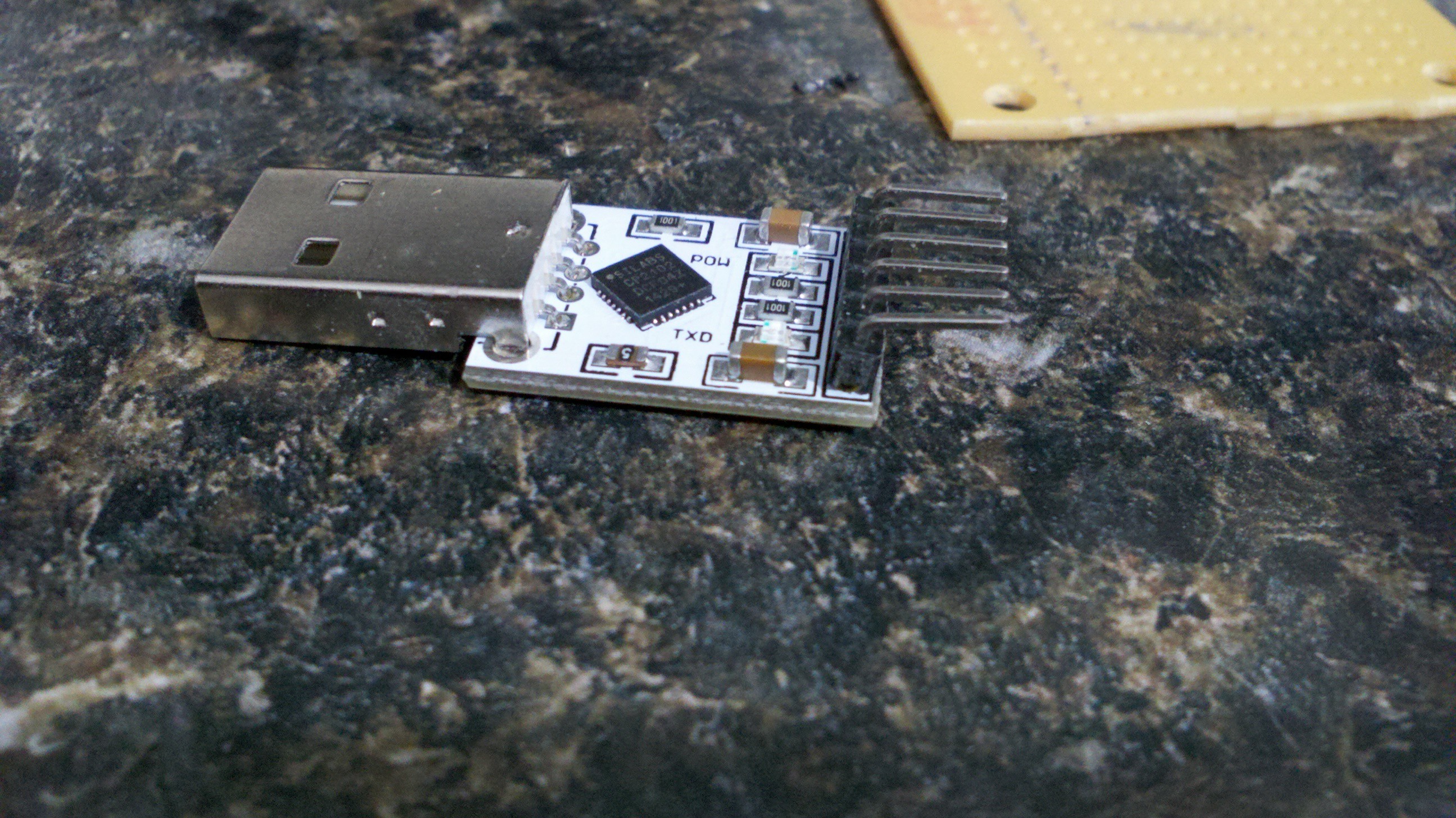
GaryI have been building a number of esp8266-01 projects. Several people have emailed me about what I used to program/debug the boards. Here is a simple development board for programming and loading firmware. Also has a couple of LED for testing GPIO output.
0%
0%
ESP8266-01 Development board
A quick and easy dev board for the esp8266-01 board
Become a Hackaday.io member
Already have an account? Log in.
Just one more thing
To make the experience fit your profile, pick a username and tell us what interests you.
Pick an awesome username
hackaday.io/
Your profile's URL: hackaday.io/username. Max 25 alphanumeric characters.
Pick a few interests
Projects that share your interests
People that share your interests
 ciborg971
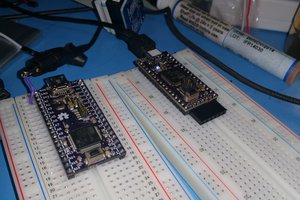
 Pal-Kristian Engstad
 TommiRouvali