0%
0%
GPS Nixie Alarm Clock
GPS controlled nixie alarm clock with IR-receiver
 Tobias Rathje
Become a Hackaday.io member
Already have an account? Log in.
Just one more thing
To make the experience fit your profile, pick a username and tell us what interests you.
Pick an awesome username
hackaday.io/
Your profile's URL: hackaday.io/username. Max 25 alphanumeric characters.
Pick a few interests
Projects that share your interests
People that share your interests
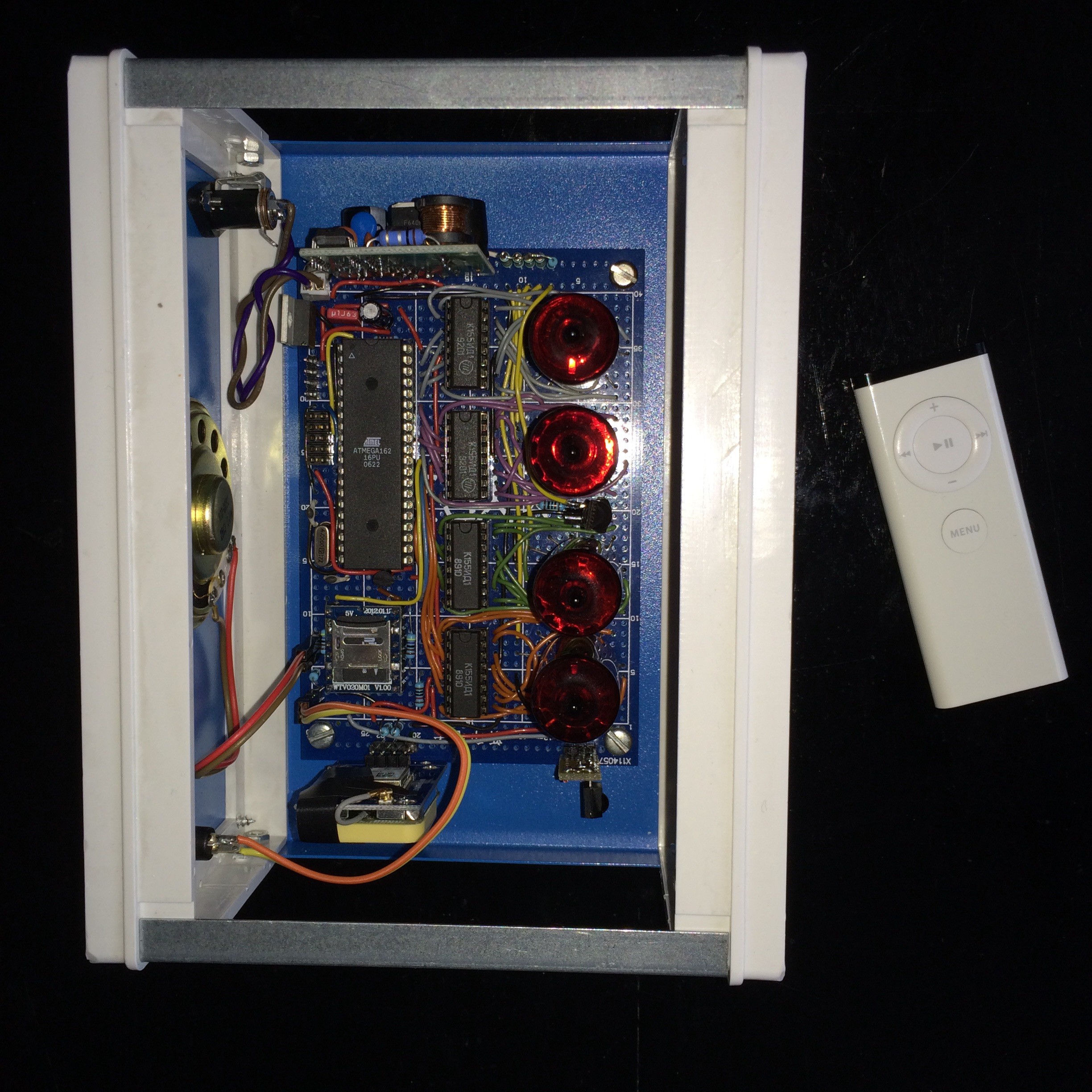

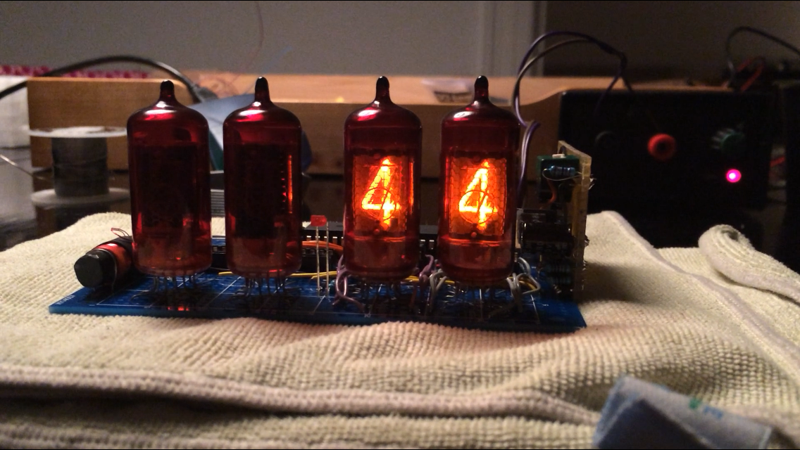 It would have been possible to use only two or even just one nixie driver IC if I had chosen a multiplexed driver design. But since multiplexing the tubes could potentially lead to problems with high-pitched noise from the PSU or the tubes themselves, and since the clock is to be placed right beside the bed, I have opted for simple non-multiplexed driver circuitry necessitating a driver IC for each tube.
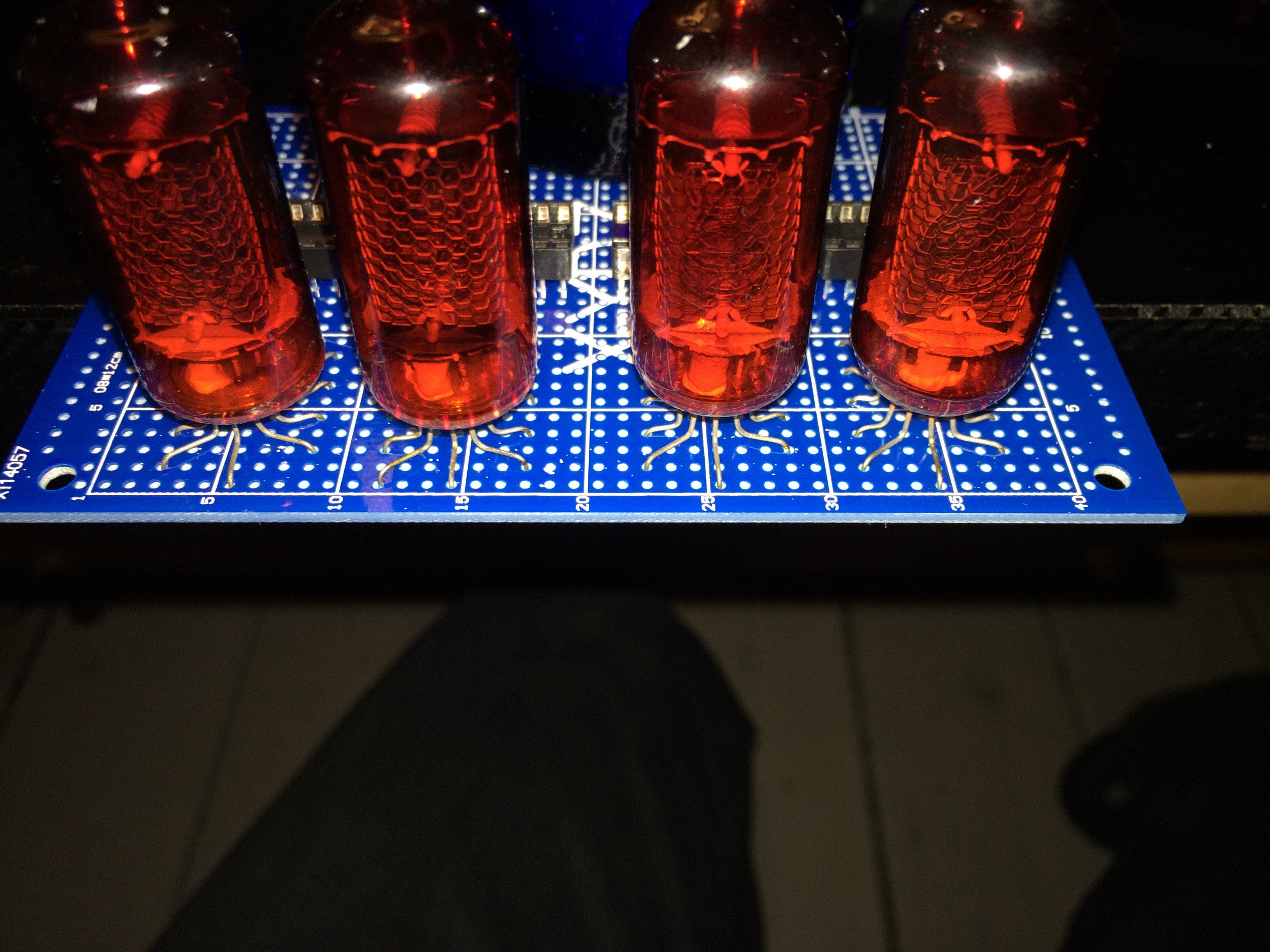

 Gigawatts
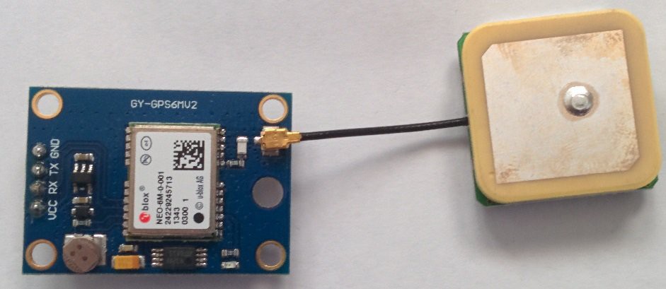
Working on a similar project, I'm wondering what the GPS reception is like, as the watch will sit indoor ? Any issues synchronising ?