 Tobias Rathje
With the CPLD, crystal oscillator and reset circuitry in place, it's time to mount the CPU and try to get it to cycle through the address space by grounding the data lines.
This is also known as free running mode, more on that here:
http://www.bigmessowires.com/2014/10/29/68k-free-run
As Steve puts it: "It seems that blinking an LED in free run mode is a rite of passage for 68K projects."
And this is exactly what I am going to do next.
I have buffered address lines A21 to A25 through the CPLD in order to avoid driving LEDs directly from the address bus. DSACK0 and DSACK1 are grounded.
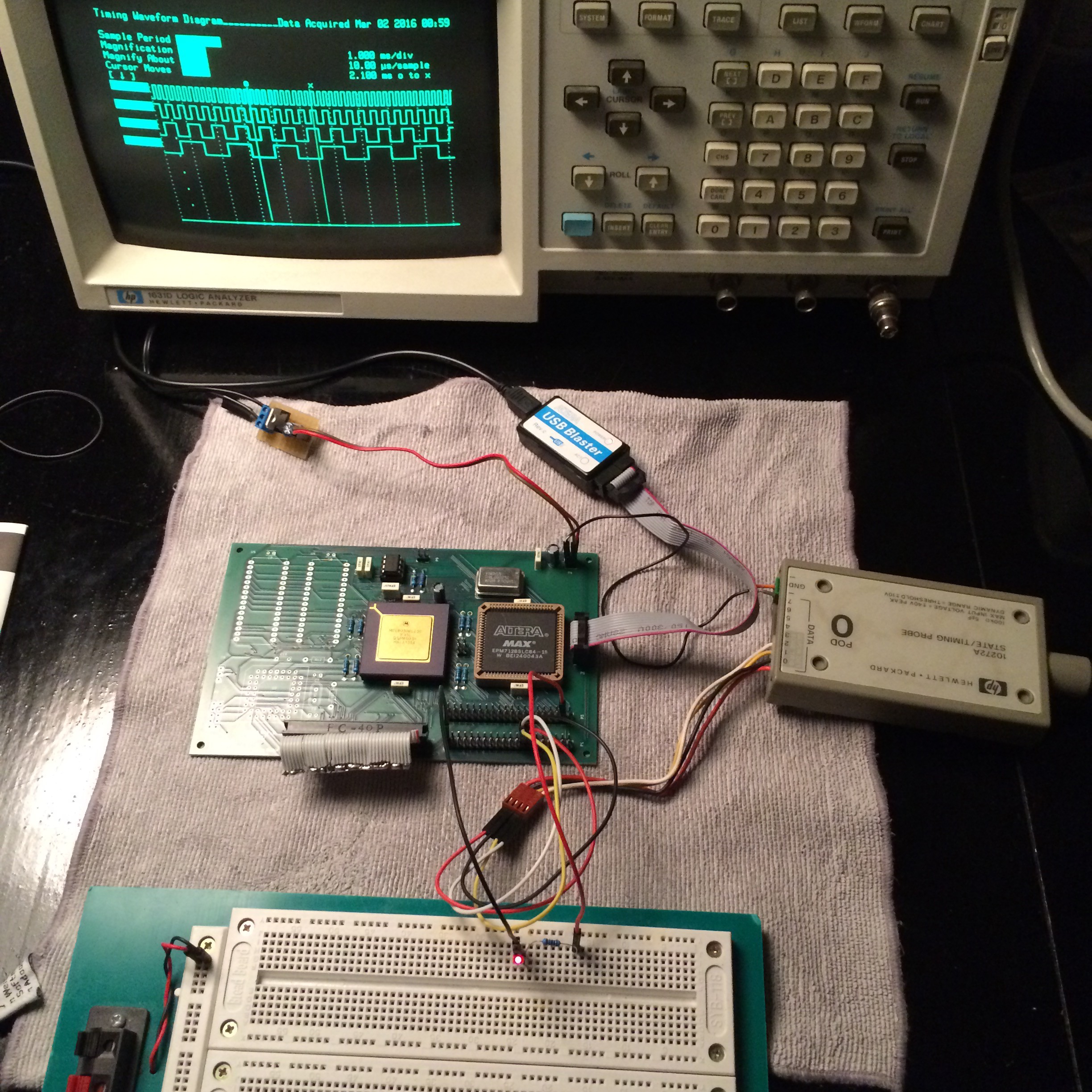
And it works! :-D
Here with the LED connected to A21 and the logic analyzer hooked up to four of the lower address lines. The plug with the frayed ribbon cable is a makeshift adapter to ground the data lines.
The result is one of the worlds most complicated LED blinking circuits. But it proves that the CPU is functional.
Discussions
Become a Hackaday.io Member
Create an account to leave a comment. Already have an account? Log In.
Nice to hear you found the problem! It's been a while, but I was about to see if I can dig up the logic schematic I used for the freerunning test.
Thanks for the comment, I am happy to see that you are working on a new project. Your original Rhombus project was a fantastic source of inspiration, and I even used your ROM code to test my first board.
Are you sure? yes | no
*discovered my problem, faulty 74LS05 driving my reset logic. awesome project, always nice to see other homebrew computers come to life
~~any chance you could provide some guidance on freerunning a 68030? I had no issue with my 68020 project at this stage, but i am not having any luck getting the 030 to respond. i'm just looking for a list of pins that need to be pulled high or grounded; i can't seem to find good info online for the 68030 and i must be missing something after reviewing the datasheet a few times.
i have all of the data pins pulled to ground, and have grounded DSACK0 and DSACK1.
i have pulled high the following per what documentation i could find: BR, BGACK, IPL0, IPL1, IPL2, CDIS, BERR, and AVEC. Additionally i have HALT and RESET controlled via a 555 timer and have verified that the start and reset lines are being asserted as needed.~~
Are you sure? yes | no