 Yann Guidon / YGDES
You can't make it simpler...
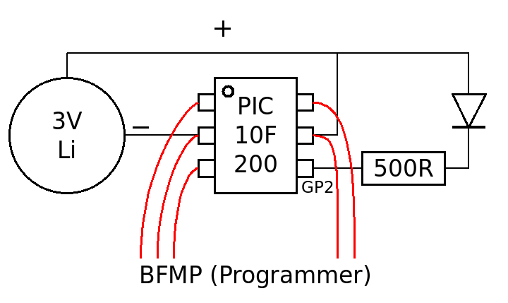
The PIC is directly powered from a primary Lithium battery.
The LED is connected to a free pin of the PIC through a resistor (the value depends on the colour and the brightness). The more resistance, the less current, the longer the coin cell lasts...
I have chosen to use a low-side switching on GP2 but this is software-configurable.
5 wires are soldered on the pins for programming purposes. Once the chip is programmed and tested, the wires can be cut.
That's all.
Discussions
Become a Hackaday.io Member
Create an account to leave a comment. Already have an account? Log In.