 Dan Royer
Over the course of the last year I've invested several thousand dollars to prototype hypocycloid gearboxes and I've learned why they don't work. I couldn't tell from the outside, and it seemed like such a straightforward idea! Well, so does the Wankel engine.
I run http://marginallyclever.com/ so that I can afford to keep making robots all day. The hope is that this way I'll gain enough experience to do something truly awesome, like make a low cost robot arm, and then teach others how to do the same. When you support my stuff you don't just get a cool robot, you help make more cool robots possible. The big show stopper in my plans for world domi-i mean robot arms, is getting enough power to move the arms from the tiny 3D printer motors available everywhere. It would be so easy if I had the right gearbox available off-the-shelf. I don't, so I tried to design my own.
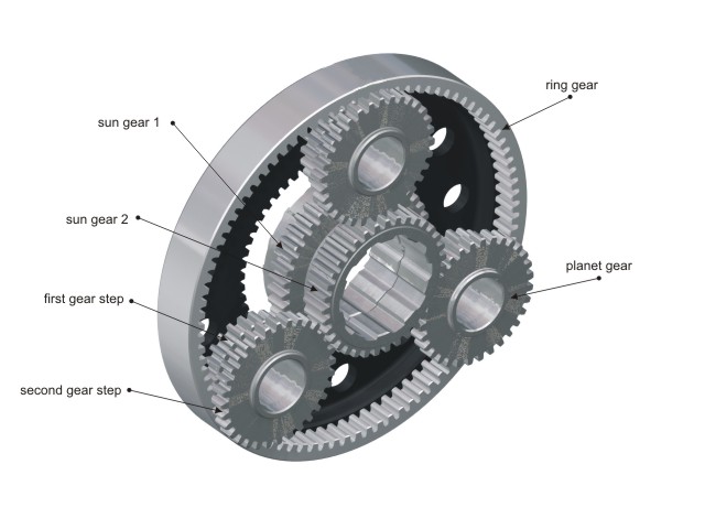 In a traditional gearbox like a sun/planet arrangement, the forces are evenly distributed - the planets are arranged around the sun. As torque on the sun increases, the force is transferred through all the planets at once to the outer gear. At worst it might break a tooth off one of the gears. The real downside to sun/planet gears (and also worm gears) is that they have backlash - while the input to a gear box is not moving there's still a bit of wiggle in the output. (At any given time there are only two teeth touching, and the distance between the teeth is the amount of wiggle.) That makes a robot very imprecise, which makes programming very challenging. I want joints and gearsboxes that are stiff - they stop exactly where I tell them to so the computer model and the real machine always match.
In a hypocycloid there is no backlash because there's always lots of teeth touching. Also, the force is uneven. Torque on either the output shaft or the input shaft causes the shaft to bend off-axis, away from the point of contact between the inner gear and the housing. As soon as this happens the interior gear starts to tilt. A tilted gear is a jamming gear, and I don't mean in a One Love kind of way.
With my machinist friend Bernie over at Coast Precision CNC and the incredible Jim Shook (who drafted all the designs) we attempted to lock down the parts, eliminate play, and experimented with different tolerances. It all came back to the same problem: the cycloid gear at the heart of the design is a problem hiding inside a solution.
There is one kind of cycloid gear, known as a harmonic drive, that works. It has a point of contact on opposite sides of the housing at the same time, eliminating the chance of bending. I was recently quoted $1650 CAD per unit for a combo RH-14D gearbox, DC motor, and encoder. $9900 for six is 10x more than I want to pay. I didn't bother asking what their closed-source controller costs.
So what's next? You keep sharing the Marginally Clever story and sending me your ideas, I keep making robots. Together we'll figure this out.
Discussions
Become a Hackaday.io Member
Create an account to leave a comment. Already have an account? Log In.
Good writeup. I think you've identified the real problem & opportunity as well. You wrote and planetary gears don't do well because "That makes a robot very imprecise, which makes programming very challenging. I want joints and gearsboxes that are stiff - they stop exactly where I tell them to so the computer model and the real machine always match."
Think about this statement - and remember - nothing is rigid for long. Nothing. Anything designed with an expectation of rigidity will die when it wears. And things designed around accuracy - those machines up getting twitchy and dangerous as they have a fit trying to get into the right position. A robot chef need to see as does the robot trash collector - anyone seeing this tech go into a shaking fit will be locking their doors.
I think your expectation of super-accuracy is unrealistic - humans aren't. As we age, how we accomplish a task will change over time as we age. If you can solve for the accuracy of the lower-cost design with better sensors - this would break the price barrier and build something resilient that doesn't require micrometer-precise gears to function.
This is certainly next-level real-time gyro and visual correction stuff - and the software required might be next level (definitely for me) - but one can start to break down the problem to identify ways of solving the smaller problems. Boston Dynamics did it - still waiting for the ifixit teardown of SPOT - those bots appear to be bouncing on relatively powerful non-precise powerful actuators - they compensate with a killer sensor package.
Solve for small-scale and this will get interesting. Sensors must not be ignored - and I think effective use of them could open up an entirely different way of thinking/'constructing bots.
Are you sure? yes | no
I want to at least to design one in solidworks and simulate it, i can't afford to machine/3D Print one (yet), I'm 4 years late, but, did you figured it out?
Are you sure? yes | no
Hi Dan I know this log is quite old but I'm gonna add my 2 cents anyway. I'm experimenting with different gears since a long time and always wanted to figure out a way to get high gear ratios with no backlash without using a harmonic drive. Harmonic drive is great but there are 2 disadvantages in my opinion:
1. It is patented and except using it for private purposes, it's out of reach
2. It relies on a very durable, deformable material which is hard to get or manufacture for hobbyists.
Regarding your problem: I ran into the same problem as you when I started with cycloid drives. If you want to prevent jamming, you have to modify the shape of the curve by removing the outmost piece of the teeth. This way, there is no contact on the opposite of the engaging side. This has no negative effect on precision or maximum torque, since there is no engagement on this side anyway. And on the engaging side, the contact happens on the flanks of the tooth and not the tip.
If you are interested in my work, I can send you some design that may help you.
Are you sure? yes | no
Hi Johannes,
I intend to design and produce (together with some students) a cycloid reduction (with a reduction of 200 and a max output torque of 600Nm)
I would appreciate it if you could send me some details about your designs
Are you sure? yes | no
Dan, been reading this and the HaD $3k fail post. Have you looked into hypocycloids since this post? AvE recently took one apart and it looks feasible _if_ you get that curve right. Would you post pics of the version you had made? I'm trying to work out where you used bearings.
Are you sure? yes | no
we were confident we had the curve right. even moderate torque on the output shaft causes the cycloid to move off center, which binds the mechanism between teeth on opposite sides of the housing. It may be possible with a much larger device that "drifts" less, but one of our design goals was a small form factor.
Are you sure? yes | no
The unit that AvE took apart had two opposing cycloid disks, which he said was a good solution to achieve rotational dynamic balance and avoid vibration but it might help with aligning the output.
How many cycloid nodes/teeth did you have? What distance eccentricity? How many output drive pins did you use? Interested in the shaft/bearings arrangement too. This is more for my education/understanding rather than me being able to diagnose the issues with that info, so don't worry if it's a big effort to write it up.
What's your target form factor and what would you grudgingly accept?
Are you sure? yes | no
I have extensive experience designing and building cycloid drives.
They don't work correctly/efficiently if the cycloid curve math is off as there's a very narrow sweet spot in the cycloid curve interface where they're mechanically efficient. The curve is point-to-point, not composed of arcs of circles. Because this three-dimensional sweet spot is so narrow rigidity and an absence of deformation due to flexing and compression are key requirements for mechanical efficiency. You may have used accurate cycloid curve math but I didn't see any clear indication of this fact in your description of your process.
Are you sure? yes | no
Im trying to build a dual stage cycloidal gear, where the input interior gear is stacked onto the gear for the output, and i cannot get the output to rotate smooth. It only rotates 1 tooth width at a time every rotation. is tooth design the cause of this?
also, the video looks to be taken down now
Are you sure? yes | no
I think cycloidal Reducer and hypocycloidal Reducer and two difference things, have you noticed the difference?
Most of the case get successful is hypoycloidal on thingiverse while little cycloidal has reported (one without photos, just model and explanation). Seems like fully featured cycloidal need more experience and know how while hypocycloidal is more easy to test with plastic.
Will you upload some picture of your experiments?
Are you sure? yes | no
they are the same thing. You may be mixing up harmonic drive and cycloidal drive.
Are you sure? yes | no
is 64:1 good enough? http://m.youtube.com/watch?v=P-Obt-9tZVo this is by mat keveny
Are you sure? yes | no
that's a planetary reducer. different system.
Are you sure? yes | no
I've drafted a hypocycloid gearbox before, but never had the chance to make it. Could you post some more info on the gearbox you had fabricated, so I can compare?
Are you sure? yes | no
A cycloidal drive is really just a variation of a planetery drive except that there is only one planet gear (typically just a bit smaller than the ring gear, and the sun gear is replaced with an eccentric drive. The hypocycloidal drive is a "clever" two-stage cycloidal drive that employs retrograde motion to arrive at a very large reduction that should (on paper) result in a very large torque increase. This is because the output speed is equal to the second stage speed minus the first stage speed. You can arrive at startlingly large reductions with 2-stage planetary drives due to the larger number of teeth involved (example (# SPR teeth/stage): Stage 1: (29,19,67), Stage 2: (26,17,60), final speed reduction: 4128:1). Unfortunately, due to the retrograde nature of the drive, you're "giving back" most of that torque, so that the most that can be realized is the torque increase of the weakest stage (1.52:1 in the example). All of which brings me to the my favorite quote and IMHO, #1 cause of entrepreneurial failures: "The human capacity for self-deception being what it is..." --Unnamed NASA Engineer on the root cause of the Challenger disaster. Incidentally, this is also know as a differential drive (not the same as in your car, unless you drive a Prius). As just noted, a two-input, single stage planetary gear is used by the Toyota Prius and makes use of this retrograde motion to effect a continuously variable transmission.
Are you sure? yes | no
By the way, if you are interested in gearboxes, you probably have seen it already, but in case you didn't, there is this guy who has been experimenting a lot with machining them: http://lcamtuf.coredump.cx/rstory
Are you sure? yes | no