 Patrick Van Oosterwijck
I'm kind of confused about where I should put this log. :) It really belongs under the #LiFePO4wered/USB project, because it's a board spin of that project, but since the heat problem exists when used with the LiFePO4wered/Pi, I decided to put it here to keep the story straight.
I've ordered some tiny heat sinks (9x9 mm) to put on the charger chip, to see if this helps keep it cool well enough to work with high power Pi's like the Pi 3.
I also learned that copper has a thermal conductivity of 385 W/m K, while FR4 PCB material only has a thermal conductivity of 0.25 W/m K. I knew copper was much better, but I hadn't realized that the difference was THAT much. So in a parallel effort, I've also improved the #LiFePO4wered/USB layout to sink as much heat away from the charging chip as possible with just the PCB copper. The old layout had a nice solid ground plane on the bottom, but no plane on the top at all, and just 3 vias near the chip to pull the heat to the bottom ground plane. The new layout has ground planes on both top and bottom, many more vias to distribute the heat, and an improved USB connector footprint that may also help sink some heat away (plus improve the mount strength of the USB connector).
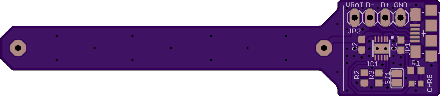
Nothing has changed about the component placement or board dimensions, so I can keep using my existing solder stencil and not incur new NRE charges at the CM. :) If I decide to use this new layout, I'll probably also have the boards made with 2 oz copper.
I'm hopeful some or all of these efforts will solve the heat limiting problem.
Discussions
Become a Hackaday.io Member
Create an account to leave a comment. Already have an account? Log In.