 JohSchneider
ok, again repopulating the board with the components grouped by function (the raspberry-zero and the powerboost 500 are already mounted)
first: soft-power
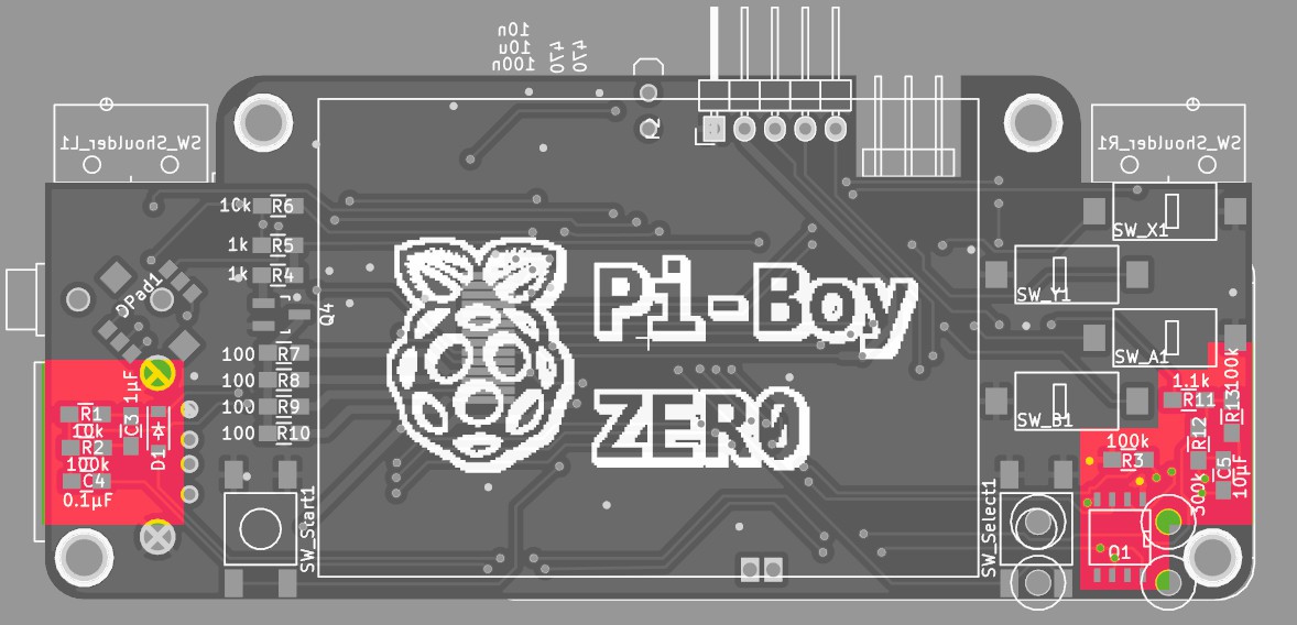
connecting the lipo battery and hitting the power button the pi boots, and pulling the gpio down powers it of :-D
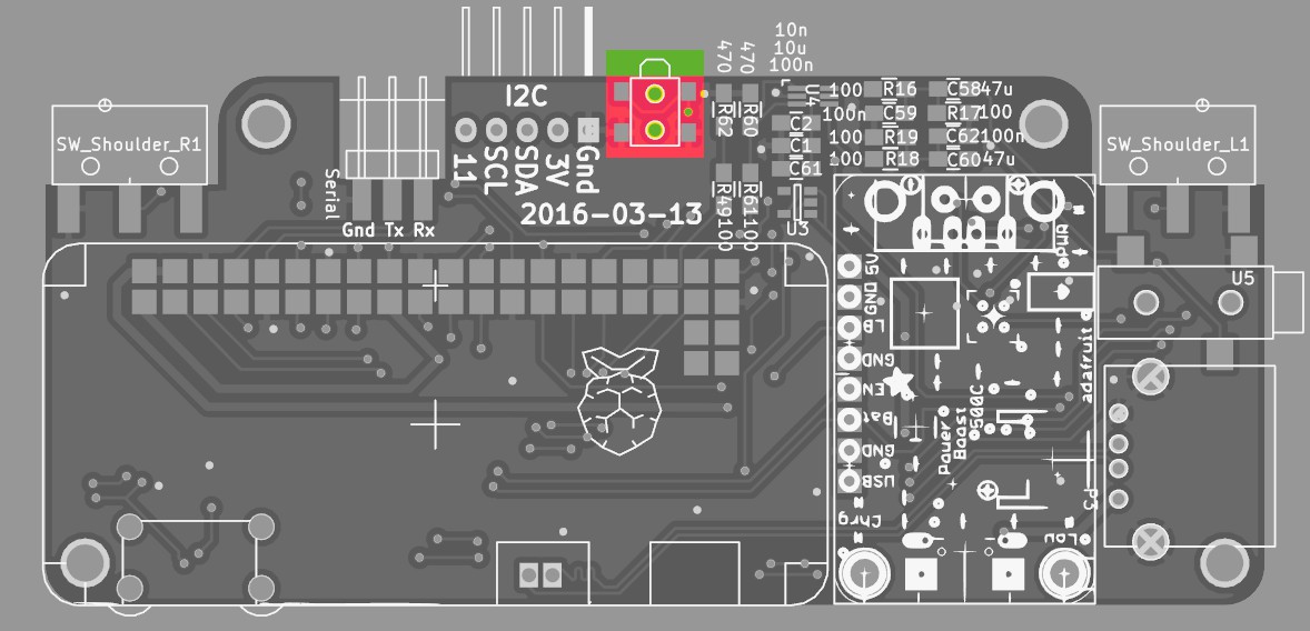
second: audio
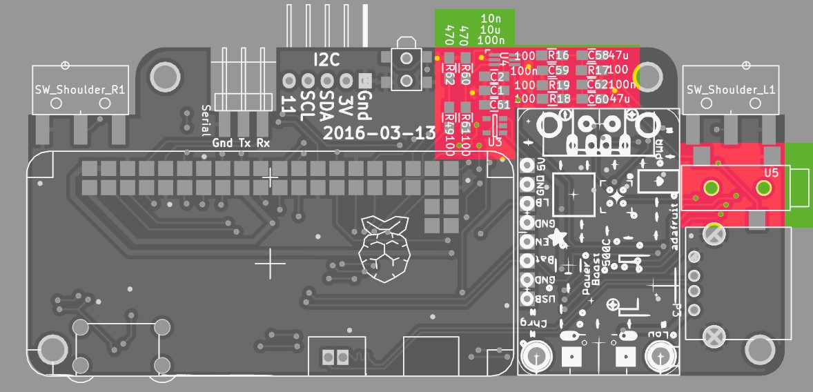
NOTE: the components in the top right corner are left/right channel = two times the same set, but their placement got a bit mixed up = is not symmetrical... oh well, just have to follow the silkscreen :-P
Testing the audio with a pair of headphones: works! :-)
(when nothing is playing - eg the channels are silent - there seems to be a tiny bit of high frequency noise coming from somewhere - and sd-io is also slightly audible... i wonder if that is just due to the anaolog/pwm nature of the system or bad board design/soldering :-S )
third: backlight and tft display:
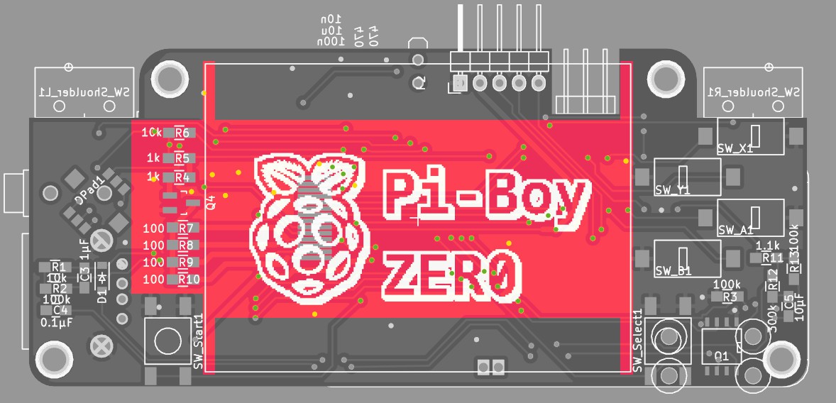
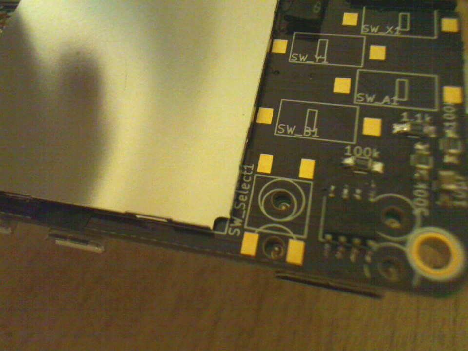
the 2.2" display is held by a metal bracket, which in turn is glued with strips of double sided tape to the donor-pcb.
a sharp knife makes short work of these:

reapplied double-sided tape to the bracket and glued it to the pi-boy pcb - aligned to the right edge of the silkscreen square
transplanting the tft screen:
* the ribbon cable of the screen was desoldered from the donor-pcb with the previously mentioned tea-candle method
* pre-tinning the contacts on the pi-boy pcb
* and finally re-soldering the 14 contact
* double/tripple check the solder-joints/solder bridges since the contact pitch is ultra small :-P
powering the hole thing up and we have picture! :-D
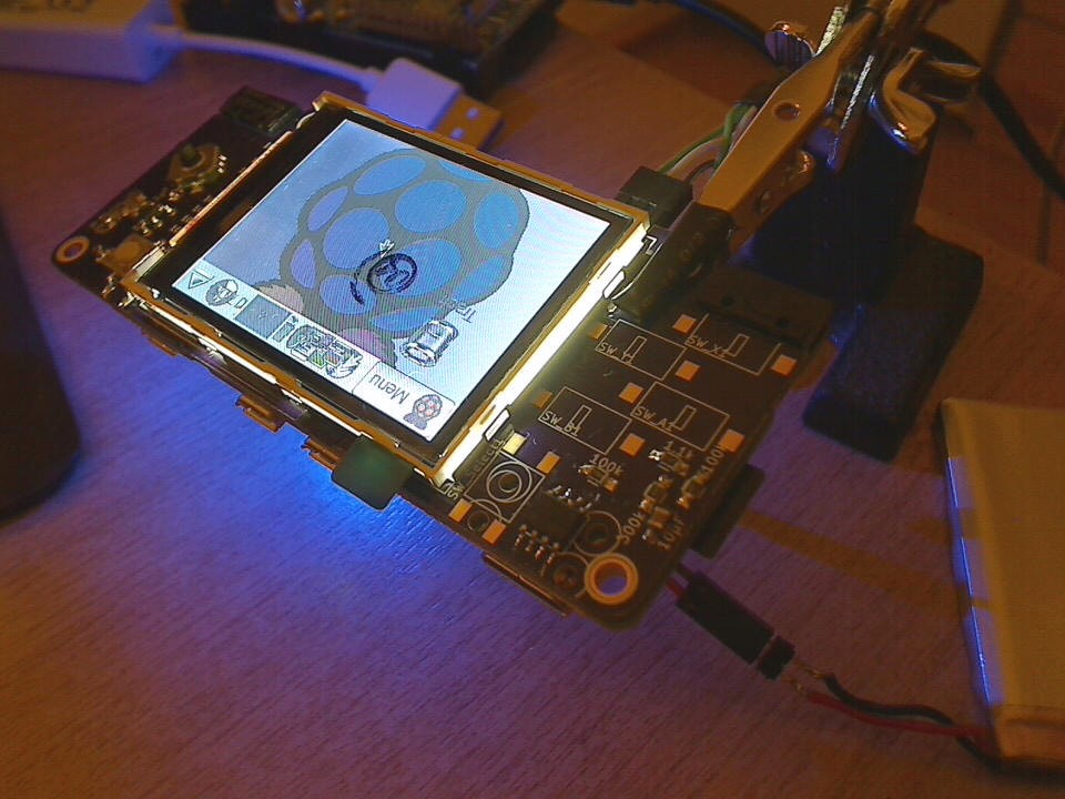 (upside down, but thats easily fixed in the config)
Discussions
Become a Hackaday.io Member
Create an account to leave a comment. Already have an account? Log In.