 Armin
ArminThis entire project started because I liked some led clocks I found online. For example: http://www.instructables.com/id/LED-Pocket-Watch/?ALLSTEPS
With no real idea on how/if I was going to build an enclosure for it I just used 4 spacer and 2 pcb's to create something. I also cut a 3mm clear acrylics front plate to protect all the leds and other compontents. This is a simple and strong first 'enclosure'. Disadvantages: I can not hide the electronics and the tap function of the accelerometer does not work when tapped on the top.

Side note: The current capacitive touch buttons are too sensitive. When I wake up (still half a sleep) and touch the alarm clock the channel changes or volume goes up/down.
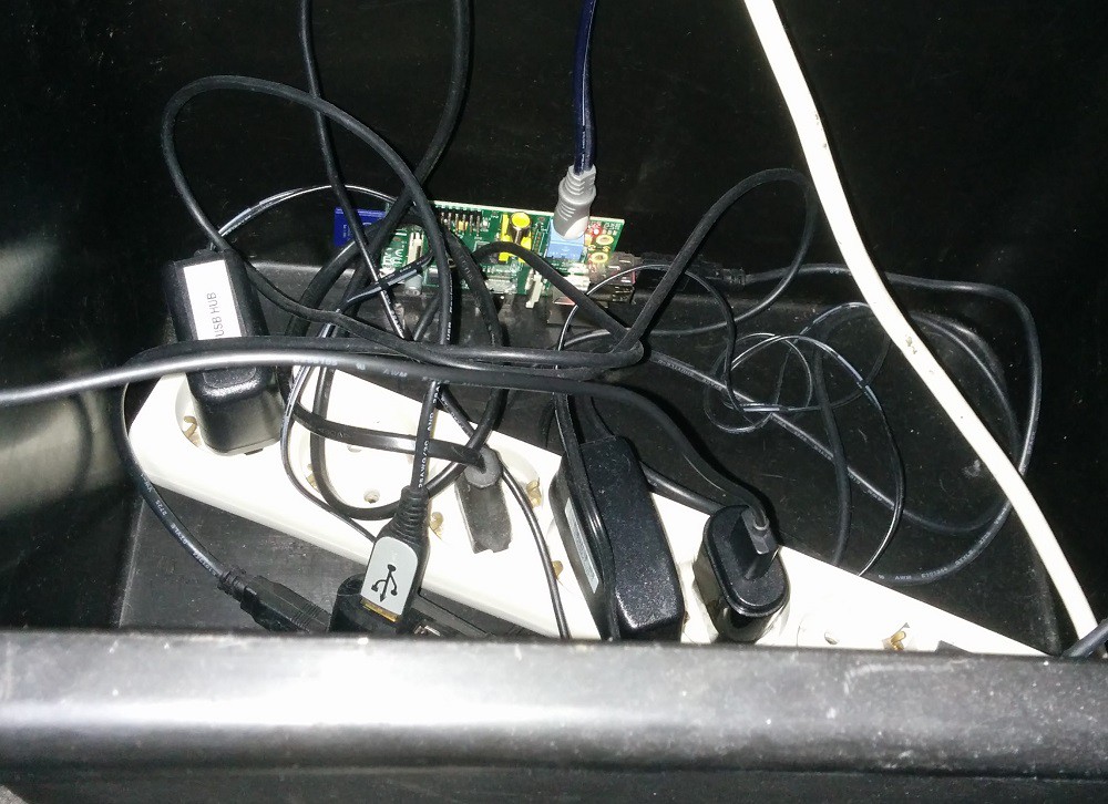
So now the electronics compartment looks like this:
So I still have to design 1 more pcb the back pcb. This pcb will (probably) have:
- A connection for the raspberry pi zero.
- USB hub for future additions and as a backup wifi and sound card
- Audio output (analog) based on the RPi 2 design (Not going for audiophile quality)
- ESP8266 WiFi
- Teensy LC interface (price from my 2015hackadayprice) capacitive touch interface and light controller
- Audio amplifier
- Wake up light based on ws2812
I have started the design for this pcb in KiCad
Discussions
Become a Hackaday.io Member
Create an account to leave a comment. Already have an account? Log In.