 Colin O'Flynn
First off - I'm planning on attending CARDIS 2014 which is Nov 5-7 in Paris, France. If you happen to be going let me know, as will have my ChipWhisperer platform with me. I'll try to bring some blank PCBs to give away, although I've got to check on my stock status!
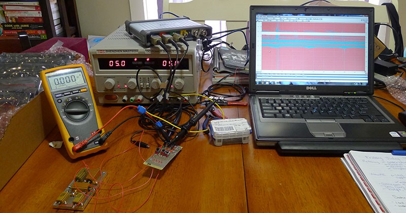
The second thing I wanted to show is the iterations of my 'product test boards'. This part of the blog post isn't part of the ChipWhisperer open-source project but related to it. As part of selling a commercial version, I want to ensure that commercial version meets certain quality specifications. So I needed ways to test the board, and I wanted to catch even small errors (wrong part values mounted, etc). My first test jig was just to verify the switching regulators on the main board. This used mechanical switches to switch a load on-off, and a mask limit test on an oscilloscope for pass/fail:
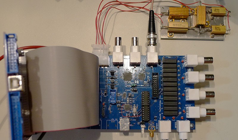
This was transitioned to a board under USB control, using a USB-HID implementation via the LUFA library. This now meant that the loads could be switched on/off electronically, with the same idea of an oscilloscope performing the mask limit testing. The left half of my test board provides this feature, but it also adds a lot more. Here is the automated power supply test jig:
There's still a lot more things that need testing! In particular there is 6 GPIO connections. These are critical to the ChipWhisperer's function, as they are expected to pass everything from communications to high-speed glitches. A bad solder joint or missing decoupling capacitor on the driver might allow it to pass a 'simple' function test (high/low), but fail when you tried to use it in real life. So I use a bank of relays to allow me to turn on/off a termination resistor for each output, and also route the pins together. Since they are I/O pins I need to test both input and output. These allow me to check:
- Drive Strength (driving high-frequency square wave into terminator resistor)
- Shorted input/output pins (one pin turned into output at a time, rest are inputs. Toggling output pin shouldn't affect inputs, if it does suggests solder bridge on translation IC)
In addition there is circuitry to check the 'AVR + XMEGA' programmer built into the ChipWhisperer, which is just a pair of chips mounted on the test board. As part of the test script it reprogram/verifies them multiple times at maximum supported SPI speed (~2MHz). There shouldn't be any errors, or it suggests problems with the physical signals.
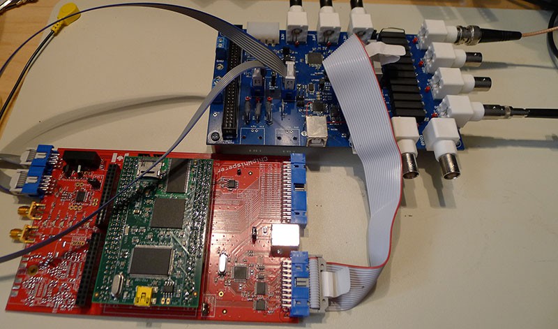
Finally there is a LVDS driver to check the LVDS clock input, and resistive loads to check the +7V/-7V power supply output voltage & ripple. The following photograph shows the rest of the connections to the test board. I haven't shown all the oscilloscope probes in either of these photos - if testing a number of boards all of the outputs are wired up to a scope, and a mask on each channel makes testing a lot quicker!
Anyway I thought that might be of interest to some people! It's part of the answer to the question "how do you make money with open hardware?". In this case my answer is that a lot of people (companies, universities, etc) want to buy a finished product that they know works. For them they would rather buy something that is known to work, and not spend even half a day fixing/building it themselves!
Discussions
Become a Hackaday.io Member
Create an account to leave a comment. Already have an account? Log In.