 Colin O'Flynn
First off - I decided to write some FAQs. I was going to add them to the main project details, but I've hit a maximum character limit in my detail! So for now I've copy/pasted them here, sorry for the big old wall of text! I also wanted to talk about my FPGA project management, see after the FAQs for those details.
FAQs
Q: Why did you use an FPGA, they are pretty complicated, can you get away using a raspberry pi or something?
A: Unfortunately it's not possible. You need to capture at a very fast rate, even something like the HackRF would be very boarderline on the capture speed. The objective is to capture on every clock edge - so even a 7.37MHz micro needs at least 7.37 MS/s, but I usually use 4x the clock rate, requiring 29.4 MS/s. This isn't even for a medium-speed ARM type device!
It's possible to use Software Defined Radio (SDR) tools, but it's far from ideal, and you'll be limited in your attack targets. The SDR tools without an FPGA cannot perform the advanced pattern-based trigger, and may not even support a basic edge-type trigger.
If you are capturing with a regular oscilloscope instead of my synchronous capture method the bandwidth requirement is about 10x the clock rate of the DUT, sometimes even (much) higher for hardware encryption implementations. In addition the FPGA adds a lot of features such as triggering based on analog pattern and super high resolution glitch generation which is impossible without the FPGA.
Q: Couldn't you just have used a Red Pitaya for the hardware?
A: Had the Red Pitaya existed when I first started this project, I probably would have tried to use it, as it's a pretty nice development environment! Unfortunately it still cannot be used as-is, so I still would have ended up with something like the ChipWhisperer in it's current form. The front-end of my OpenADC adds up to +55dB gain which is software adjustable, whereas the Red Pitaya has only a fixed small range which would require an external amplifier. The OpenADC also has a huge analog bandwidth (beyond the sample rate for undersampling applications, which the synchronous sampling can exploit), whereas the Red Pitaya limits you to the Nyquist rate. Finally the ChipWhisperer still adds a bunch of extra features such as the target programming interface, power supplies for probes, high-slew-rate level translators for clock input and output, an external PLL chip for low-frequency operation, and a high-speed USB interface.
Q: Couldn't you have just used GNURadio as a software framework?
A: My original intention was to use GNURadio as a GUI, since it has a lot of built-in blocks such as filters which would be useful. But the requirements of side-channel analysis are different enough from communications systems to make the use of GNURaido seem like a hack, and would require considerably more work than my current GUI.
In addition the install procedure for GNURadio on Windows can be pretty complicated. I really wanted as straight-forward an application as possible, and I felt that the barrier to entry for most people would be considerably raised if using GNURadio. Long-term, I may end up with blocks for GNURadio that perform some of the analysis.
Q: What's the deal with the commercial version?
When I first started this project, one of the main requests was that people wanted to just buy the finished hardware. Spinning out of that is the complete commercial version with fancy waterproof case etc. It's no different from what you can build yourself, but comes fully tested and in a nice storage case!
The ChipWhisperer name is a registered trademark, and this was done in part to allow me to reliably sell a commercial version of the project. Only products sold via NewAE Technology Inc are allowed to use the ChipWhisperer name, but this doesn't stop someone else from selling a version under a different name. I want to ensure that the commercial version is of the highest quality, and wanted to avoid someone selling a cheap poorly-assembled version that at first appearance appeared to be a product from my company!
Xilinx Project File Managment
The second part of this log post is a little more interesting (I hope). The Xilinx ISE tools use an XML-based project file. Unfortunately it's difficult to commit that project file to the repository - it uses all sorts of automatically overwritten properties, including the version of the software:
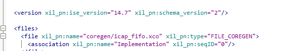
What this means is that if you have two people working on the project, you are almost guaranteed to have merge conflicts, since if they have different versions, the file will change on both their machines in that line. Since each install is >10GB people tend to be pretty slow up updating the version of their software.
The other issue is that I want to support several versions of the hardware. This means supporting different FPGA devices with different modules enabled. This would otherwise mean multiple project files, and changes would have to be carefully managed across them. This is a recipe for failure! There is even COREGen blocks with are automatically generated, and normally have tons of options you must specify. For someone to port the design to a slightly different FPGA (different package of same FPGA, different device within same family, etc) they must manually recreate all those blocks. And if they forgot to set an option properly the design won't work.
I decided to fix this with a bit of Python, and I'm going to be forever grateful I did. Basically there is one '.in' file, which contains simple lines. The beginning of the file looks like this:
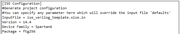
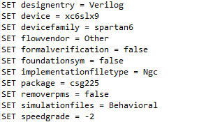
The InputFile is a 'template', which is really just a default Xilinx ISE project file. The next section simply finds parameters and overwrites their values, allowing you to overwrite ISE version, device type, etc. For example if you need to set a specific map command-line option, we can do that as follows:

Note how the option is set in the resulting .xise project file. Easy! If you want to generate a .xise file for another package, you simply change that one 'package' line as appropriate.
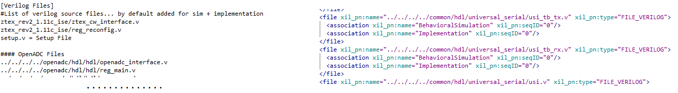
The next section of the input file has a list of all the source code. These are inserted into the .xise project file as such:
Finally we come to the COREGen files. This section can be used like the verilog sources, but the interesting part is the ability to autogenerate COREGen files based on an input. The first section simply lists all the COREGen files:
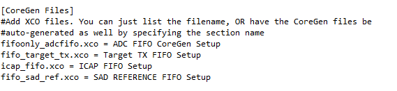
The next sections can list details of the files. For example for my ADC FIFO I can configure the depth. Not only does it set the proper depth in the resulting .xco COREGen file, it also calculates other required parameters such as output depth, assert values, etc:
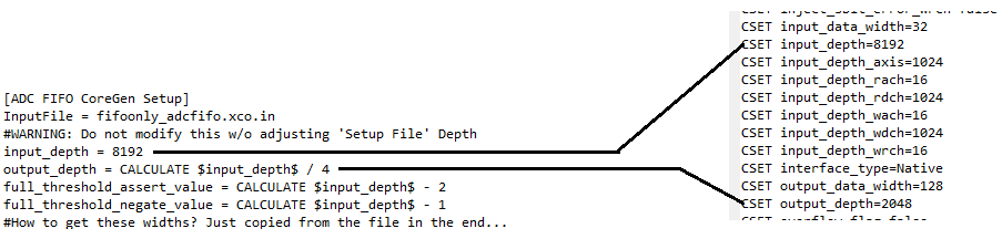
Finally, the resulting .xco files are kept consistent with the device package that was configured earlier in the project file! So you no longer have to manually recreate the .xco COREGen files, they are automatically generated for you based on the single input settings! Yah!
The final section of the project file managment is the ability to write a "define" file. If you look back at my example Verilog files, there is one (setup.v) that is without a path. But it does have a name, which links to the section name in the project file:
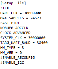
This will simply create a file called setup.v, where the above will be defined. So the file looks like this:
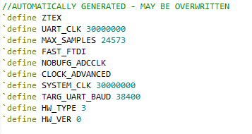
For my project that file defines the hardware in use. It is included in each Verilog source file, and if there is hardware-specific configuration it can be managed with simple `ifdef `endif sections that include/exclude certain modules. The result is I end up with a single input file that defines everything about the FPGA project. You can run a Python script which then generates the 'dirty' ISE files. If we need to add a new configuration option to the project, you can trivially add it to the original project file.
Discussions
Become a Hackaday.io Member
Create an account to leave a comment. Already have an account? Log In.