 spencer
So, after waiting for what seemed like an eternity (it really wasn't very long at all), I got a purple padded envelope through with OSHPark on it. Inside was 3 copies of my Pi Zero to RC2014 PCBs!
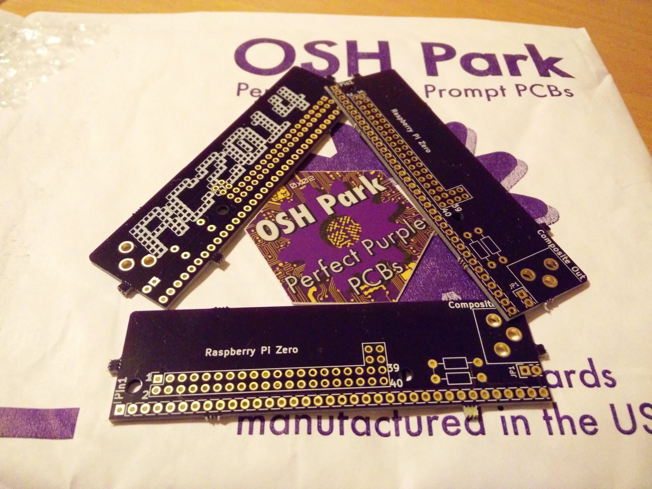
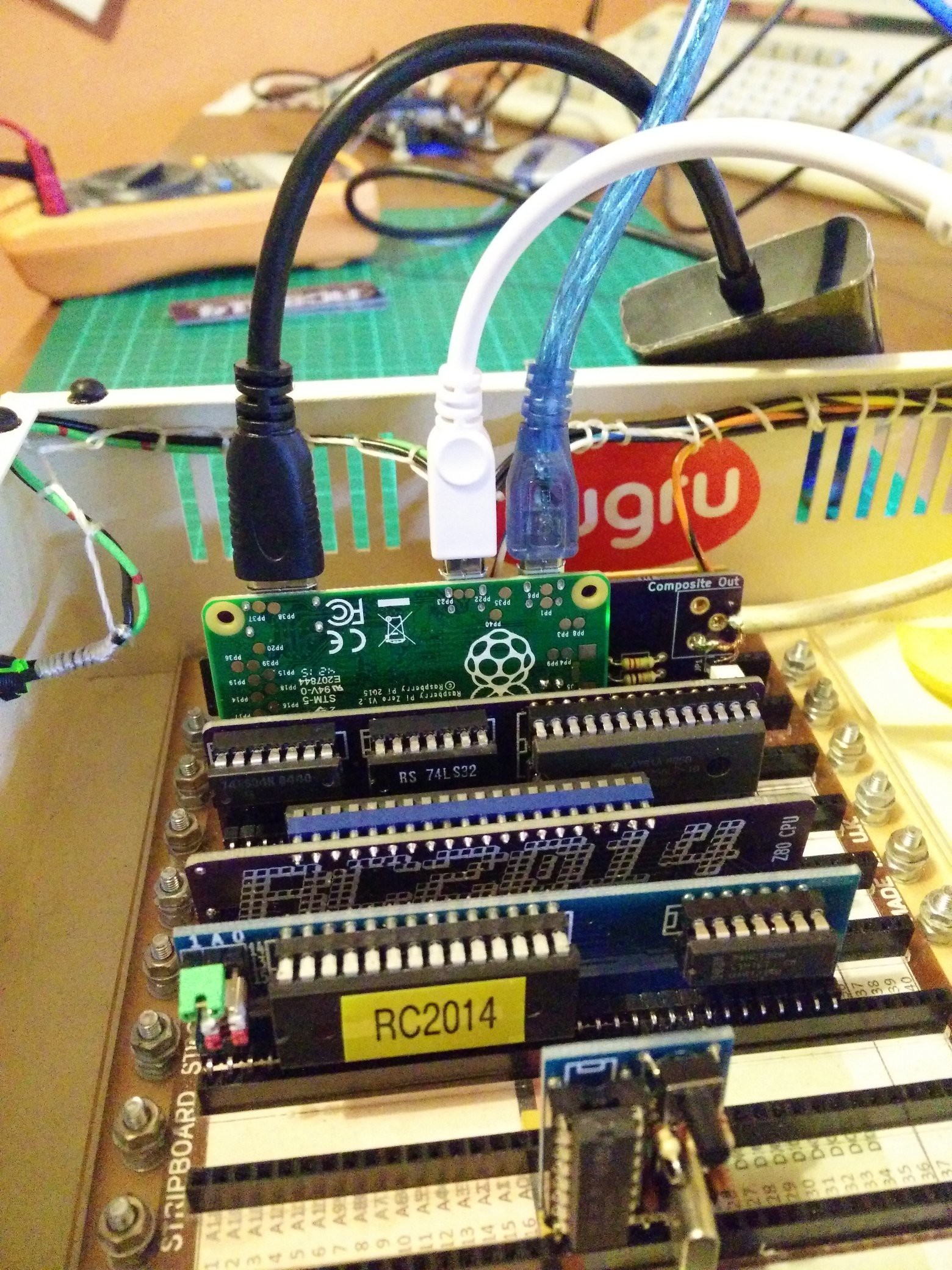
A quick check of the boards confirmed they'd been manufactured exactly as expected (ie perfectly!). Time to fire up the soldering iron and get testing!
As it was a test board, and I am tight when it comes to connectors, I didn't populate the entire 44 pins worth of sockets the Pi would connect to. It only needed a few for connectivity and mechanical location afterall;
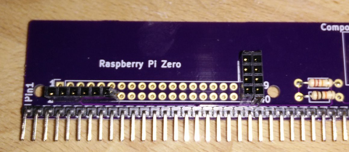
Due to not ordering the components in time, I didn't have the phono socket for the composite output, so that would have to be bodged up for now. But, hey, it's a prototype, right?
The Pi itself fitted a treat. Even the holes I'd put in for PCB support lined up, although the connector seems to hold it well enough.
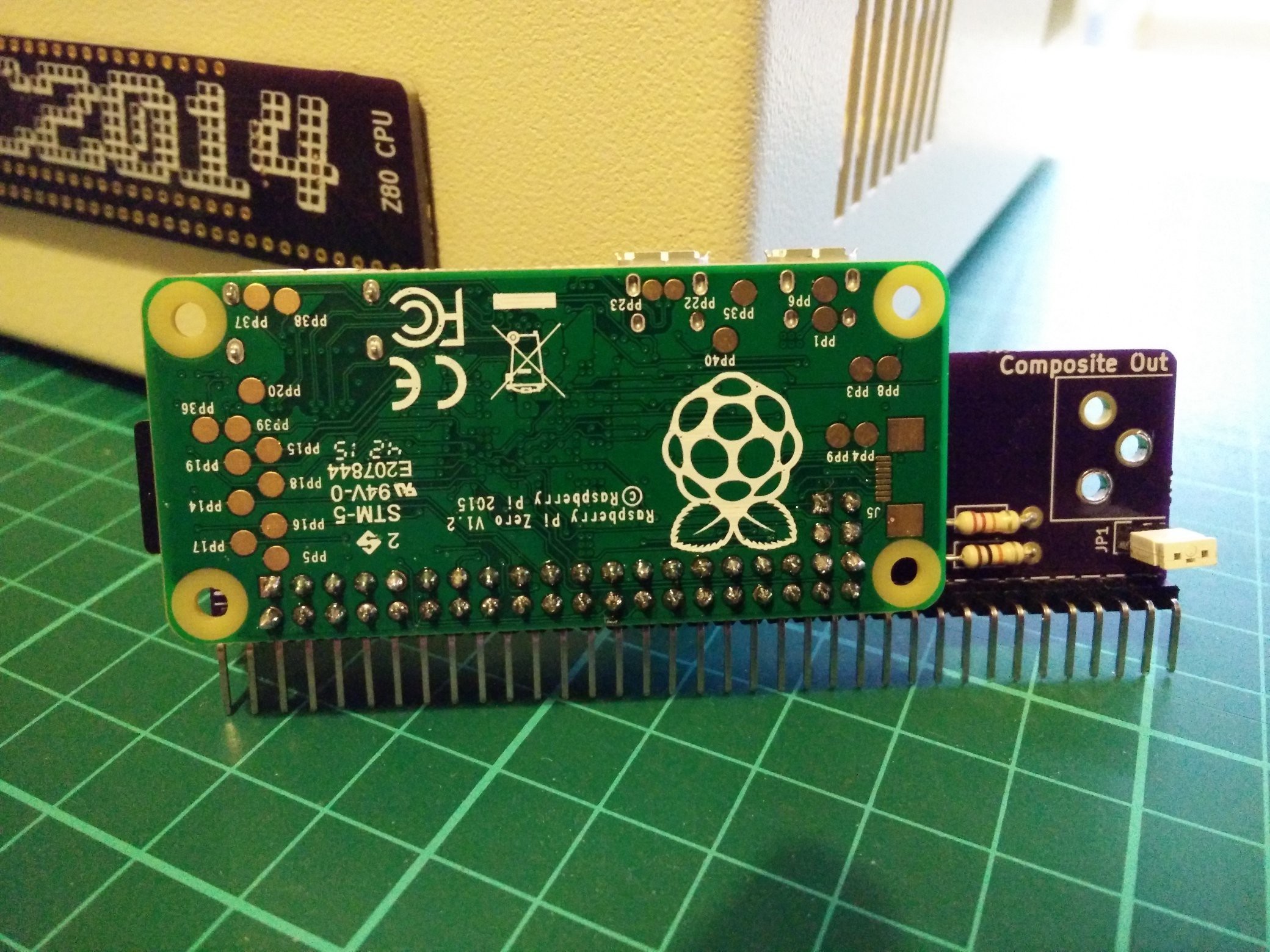
Initial testing proved it worked well through a mini-HDMI to VGA adapter. I soldered on a temporary lead to test the composite output, and that worked too, although the picture wasn't as great as I'd hoped. Possibly the composite traces on my PCB were too long, too thin or not shielded enough, or possibly the temporary connection was just a bit poor.
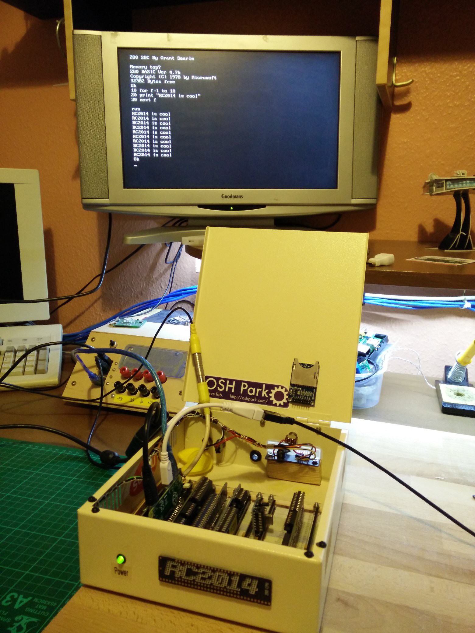
A couple of days later, the phono sockets arrived so I could complete the board. The socket fitted perfectly, which was great! However, no matter what I did, I couldn't get a picture through it! Eventually, it became apparent what was wrong; The ground and signal were reversed coming out of the phono socket!
If you recall from the previous log, this is a component that I had to add to Kicad manually. I took great care in making sure all the measurements and physical aspects were correct... although I paid less attention to the electrical side of things. In my defense, though, it seems perfectly reasonable that the center pin on a "triangle" of pins would be the signal and the other two would be ground, right? Wrong!
This, in fact was a good thing because it taught me several things; Read the datasheet. Read the datasheet again. Check the datasheet. Do not make assumptions. And READ THE DATASHEET!
Well, at least I had a working video out from the HDMI socket, so I could start looking at getting the Pi optimised for being a dumb terminal.
Discussions
Become a Hackaday.io Member
Create an account to leave a comment. Already have an account? Log In.